
MachPro TP400 Probe Wiring and Configuring
{{@2007#bkmrk--1}}
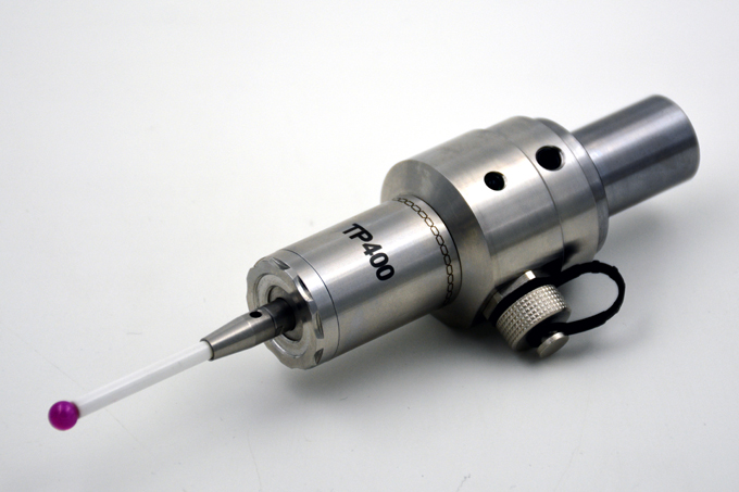
How-to guide
Scope
This procedure shows how to wire a TP400 touch probe to an M31 motion controller digital input. It also shows where to connect the cable shield.
Terms
-
0 V DC: The DC power return conductor for a 24 V DC supply.
-
PE (Protective Earth): The safety earth bond for the enclosure and bonded devices.
-
Chassis ground: The metal enclosure bond point. Chassis ground is bonded to PE.
-
PNP input: A digital input that turns ON when it receives +24 V DC relative to 0 V DC.
Prerequisites
-
A regulated 24 V DC power supply for field I/O.
-
A free M31 digital input configured as a probe input in MachPro.
Procedure
-
De-energize the cabinet.
-
Route the TP400 probe cable separately from motor and VFD (variable frequency drive) output cables.
-
Connect probe power:
-
Connect TP400 +24 V DC to the 24 V DC field supply.
-
Connect TP400 0 V DC to the 0 V DC field supply (the same 0 V DC reference used by the M31 inputs).
-
-
Connect the TP400 probe output to an M31 input:
-
Connect the TP400 trigger output wire to the selected M31 input terminal.
-
Make sure the input is configured in MachPro as the probe input.
-
-
Connect 0 V DC correctly (recommended cabinet practice):
-
Tie all 0 V DC terminals (power supply 0 V, drive I/O 0 V, M31 I/O 0 V) to a single 0 V / ground bar.
-
Bond the 0 V / ground bar to PE at one place only.
-
-
Connect the probe cable shield (updated):
-
Connect the probe cable shield to the enclosure ground lug (PE/chassis ground) at the cabinet entry point.
-
Do not connect the cable shield to an M31 0 V terminal.
-
Do not connect the shield at the probe end unless you have a defined EMC (electromagnetic compatibility) plan and equipotential bonding.
-
Use a 360° shield clamp or gland if available. Keep any pigtail as short as possible.
-
Reference
TP400 electrical notes
-
The TP400 uses shielded cable.
-
Input power is 24 V DC (±10%).
-
The TP400 output load current limit is 50 mA (maximum).
Shield termination rules of thumb (for this application)
-
Terminate the shield at one end only (cabinet end) to reduce ground-loop risk.
-
Prefer a low-impedance, 36 “pigtails”). lug is better than an M31 0 V terminal
A cable shield workending the noise to ground through a low-impedance path. A shield that is not grounded, or is grounded through a high-impedance path, is less effective.
If you connect the shield to 0 V DC at the controller, shield current can flow in the same conductors used as the signal reference for inputs. This can shift the input reference and cause false input transitions.
Connecting the shield to chassis ground (PE) keeps shield current out of the 0 V DC signal reference. Rockwell’s wiring guidance shows this approach: ground the shield at one end and connect it to a chassis mounting bolt.
About pigtails vs 360° clamps
Single-point terminations that use a drain wire or pigtail can reduce shielding effectiveness because the exposed length adds impedance and can radiate or receive noise. 360° terminations perform better across a wide frequency range.
Troubleshooting
-
Symptom: Probe trips randomly when the spindle starts or during rapid moves.
-
Verify the shield is connected to PE at the cabinet entry and not to M31 0 V.
-
Verify the 0 V / ground bar is bonded to PE at one point only.
-
Re-route the probe cable away from motor/VFD output cables.
-
{{@2016}}