MachPro Input Mapping for Tool Setter and Probe
{{@2007#bkmrk--1}}
Purpose
This document tells you how to map (assign) a physical input to a MachPro probing signal for:
-
a tool setter (tool length measurement switch or plate)
-
a probe (part probe, touch plate, or ohmic probe)
Definitions
- I/O: Input/Output.
-
Tool setter: A device that triggers when the tool touches it. MachPro uses it to measure tool length.
-
Probe: A device or circuit that triggers when it touches the part (or a probe plate). MachPro uses it to find part edges, tops, and features.
-
Input signal: A software “name” for an input state (active or inactive) in MachPro
- Active-low / active-high: The electrical logic level that the software treats as “active.” MachPro let you set this per input.
Safety
-
Keep the Emergency Stop (E-stop) circuit available and tested before you do probe moves.
-
Make sure the probe signal is inactive before you start a probing move.
Tutorial
Quick check: confirm the input triggers
- Click the Service tab at the bottom of the screen, then the Machine I/O tab at the top of the screen
-
Find the probe status indicator for the probe signal you plan to use (for example, Probe or Probe 1).
-
Trigger the device by hand:
-
push the probe tip gently to the side
-
touch the tool setter
-
short the probe plate circuit (if you use an ohmic/touch plate)
-
-
Make sure the correct indicator changes state (active/inactive).
If the indicator does not change, do the mapping steps in the next sections.
How-to
Map the probe or tool setter input
When you installed MachPro with your motion controller, the motion controller plugin added all of your I/O ports to the device and inputs options for signal mapping.
-
Go to Configure > Control > Input Signals.
-
Decide which probe signal you will use:
-
-
Probe (G31 / G31.0)
-
Probe 1 (G31.1)
-
Probe 2 (G31.2)
-
Probe 3 (G31.3)
-
-
-
Enable the selected probe signal.
-
Map the selected probe signal to the physical input:
-
Select your motion controller in the Device column
-
Select the input you are using on the Input Name column
-
-
Set the correct active state (active-low or active-high) for that input.
- The State column will be green if that input is currently active. Use that to verify the input mapping and Low or High State configuration
-
Save the configuration.
-
Test the mapping in Diagnostics:
-
Manually trigger the probe or tool setter.
-
Make sure the correct probe indicator changes state.
-
In this example, the I/O device is a Beckhoff EK1100. The inputs are all DI (Digital Inputs) and the slices and ports are numbered. The plugin will create a similar numbering system for your motion controller's inputs. 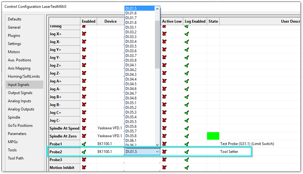
Map the tool setter overtravel (limit) input
Use this when your tool setter has a second switch for overtravel (fault protection). This circuit is usually wired Normally Closed (NC) so that its state will change if there is overtravel on the device, or if the input cable is cut. MachPro uses the Global Monitoring System (GMS) to disable the system when the overtravel limit is triggered.
-
Wire the overtravel switch to a digital input.
-
Go to Configure > Control > Input Signals.
-
Map the overtravel input to an unused input or the Z negative limit signal.
-
Test the overtravel switch:
-
Trigger it by hand (only if it is safe).
-
Make sure MachPro shows the limit/fault state.
-
-
Keep the overtravel signal separate from the probe signal. A common setup is:
-
main tool setter switch → probe signal
-
overtravel switch → Z-- limit or a dedicated fault input
-
Global Monitoring System (GMS) Adjustments
Pull down Configure -> Plugins -> Global Monitoring System
There may already be a monitor configured for the Tool Setter Limit (Over travel).
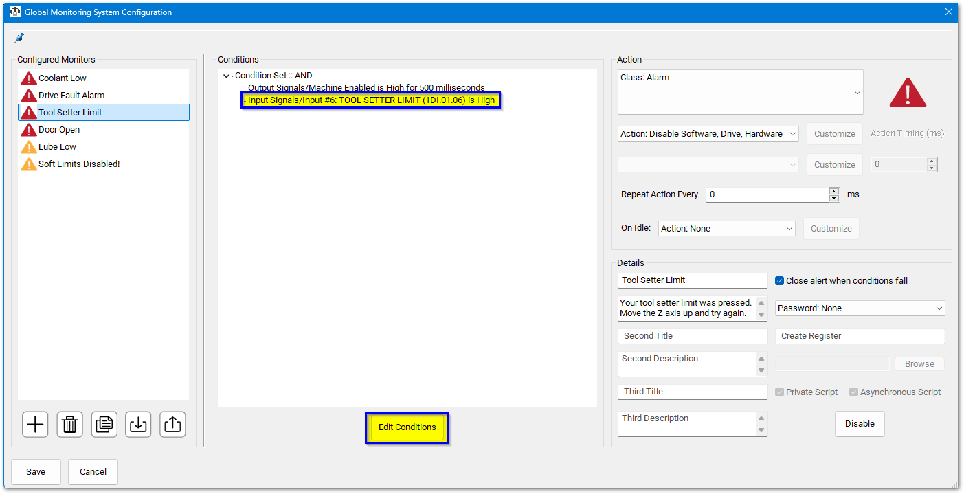
This monitor is configured to trip immediately when the machine is enabled, and the input signal at DI.01.06 goes high. If that is not where you mapped the tool setter limit, then click the Edit Conditions button at the bottom of the center pane.
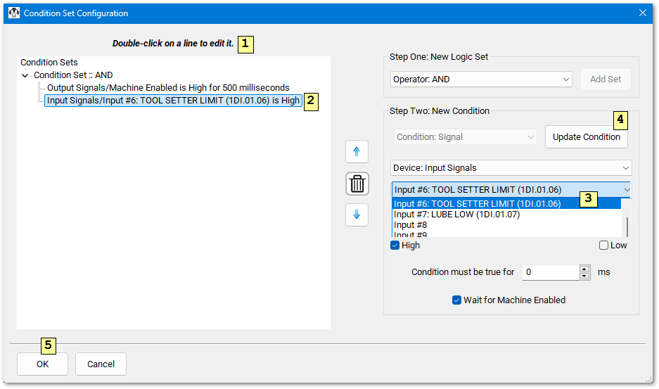
After you have updated the condition to monitor the correct input signal, click OK to close the condition editor. Click the Save button in the lower left corner of the main GMS configuration screen to save all changes.
This is the more complete documentation for GMS MachPro Global Monitoring System
Troubleshooting
-
Probe indicator is always active:
-
wrong active-low/high setting
-
wiring is reversed (NO vs NC)
-
probe circuit is shorted
-
probe signal is mapped to the wrong input
-
-
Probing routine fails to start or gives wrong results:
-
probe signal is not mapped in Input Signals
-
wrong probe code selected (G31 vs G31.1, etc.)
-
-
False triggers (noise):
-
add noise filtering/debounce in the plugin (if available)
-
use shielded cable and correct grounding
-
Explanation
MachPro reads physical inputs from your motion controller. Each input must be mapped to a software signal so MachPro can use it.
Tool setters and probes both use the MachPro probing system. That is why they map to probe signals (Probe, Probe 1, Probe 2, Probe 3). The probing G-code selects which probe signal MachPro watches during the move (G31, G31.1, and so on).
{{@2016}}