
Yaskawa Brake Troubleshooting and Sigma-X Motor Cable Pinouts
MachMotion | Sigma-X rotary motors | Revision 1, November 11, 2026
Use this manual to isolate a brake command, relay, power supply, cable or motor fault. Start with the full motor model and the actual job schematic. The motor power voltage (200/400 VAC class) is not the brake supply voltage.
Before testing
Qualified technicians only. Mechanically secure any gravity-loaded axis before disconnecting wiring or releasing a brake. Isolate all power sources, follow the exact SERVOPACK discharge procedure, and verify absence of voltage before resistance/continuity measurements or unplugging a connector. Live measurements require the site electrical-safety procedure and suitable instruments.
Do not jog against a suspected applied brake, bypass safety functions, or jumper every brake relay. A holding brake is for holding position; it is not the normal means of stopping a moving axis. A released brake can allow a load to fall.
Start with these four facts
| Record | What to identify |
|---|---|
| Motor | Full SGMX... model, voltage class and C/E brake option |
| Cable | Part number, power/brake vs encoder, each connector or extension |
| Drive | Exact SERVOPACK and interface; /BK output assignment |
| Circuit | Job drawing revision, relay/socket, supply and suppression parts |
Quick fault split
| Observation | Next useful test |
|---|---|
| No relay indication | Measure relay coil voltage; trace the /BK command and its return |
| Relay indicates, no release | Measure across brake feed and return under connected load |
| Voltage at panel only | Compare panel and motor-end voltage, including return path |
| Correct motor-end voltage | Isolate brake coil resistance and verify mechanical release |
| All three axes affected | Check common supply/return first, then each branch and mapping |
A relay LED proves neither contact conduction nor correct axis mapping/timing. A click or sound is supporting evidence, not proof of brake release.
Divide and conquer: test one axis
1. Establish the symptom without forcing motion
Record whether the noise starts at enable or at jog, which axes are affected, and any alarms. The shop discussion reported loud screeching and restricted movement; those observations suggested a brake problem but did not establish the cause. Keep mechanical binding, coupling alignment and servo tuning in the diagnosis if brake release checks pass.
2. Separate command from the power circuit
Check the expected /BK state in the drive and the voltage directly across the relay coil. If the drive changes state but the coil does not receive its rated voltage, trace the interface cable, output configuration, coil return and socket wiring. Use the actual drive manual; CN1 and interface-board pin assignments differ.
If coil voltage is correct, check the switched contact path. Verify COM/NO against the relay/socket diagram; a lit relay can have a wrong socket pinout, damaged contact or insufficient contact rating. Measure voltage drop across the closed contact while the brake is connected.
3. Separate the panel from the cable and motor
Measure DC voltage across the two brake conductors, not just one conductor to chassis. Compare the supply, relay output and safely accessible motor-end connection under load. An unplugged cable can show normal voltage even when a poor connection cannot carry current. Use a proper mating breakout; do not spread or short connector contacts.
4. Split cable from motor with power isolated
Disconnect the motor cable at the motor. Measure resistance across the identified brake contacts on the motor receptacle. Then disconnect the cable at both ends and isolate relay/suppression branches. Check each brake conductor end-to-end, cross-conductor isolation, and isolation to PE/shield. Flex the cable gently while checking for intermittent opens. A continuity beep alone does not establish current-carrying capacity.
An open motor-side reading points toward the brake circuit/connection; very low resistance requires comparison with the exact motor specification. A correct motor-side reading with a bad cable reading localizes the fault to the cable/connectors. External diodes can distort readings if left connected. Do not megger an encoder or connected electronics.
5. Verify the axis mapping and sequence
With the load secured, observe each drive command and its corresponding relay/branch one axis at a time. Record a drive-to-relay-to-motor map. Confirm release before commanded motion and correct application during shutdown using the model-specific timing chart. Do not use a blanket delay or a permanent manual override.
How the relay circuit works
The original MachMotion drawing D0004 shows a 24 V supply, a drive-interface brake command, a relay coil, and a normally-open contact feeding the motor brake. It is a legacy reference; verify the current job drawing before using its interface or relay terminal numbers.
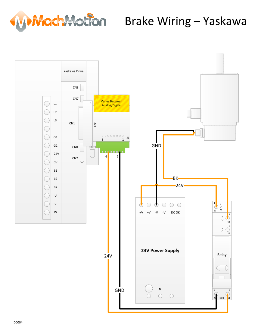
MachMotion D0004 - Brake Wiring - Yaskawa. Interface wiring varies between analog/digital. Click image to enlarge.
| Element | Function / check |
|---|---|
| Coil A1/A2 | Receives the control command; confirm coil rating and polarity markings |
| COM / NO | Closes the brake supply path when commanded; check the actual socket |
| Motor brake | Receives its rated DC supply to release; loss of supply applies it |
| Suppression | Separate brake-coil and relay-coil suppression may be present |
A plain DC flyback diode is normally reverse-biased in operation (band/cathode toward positive). Follow the specified suppression circuit: replacing a diode with a different suppressor can change response time. Bare brake terminals may have no polarity, while external diodes and polarized relay modules do. Do not assume two black wires make the whole circuit polarity-free.
Choose the connector before probing
The Odoo catalog includes SGMXJ, SGMXA, SGMXG and SGMXP brake products, with 200 V and/or 400 V variants. This is connector-family coverage, not a claim that every catalog variant is stocked or commonly installed. C indicates a holding brake; E adds an oil seal and holding brake in the catalog models reviewed. Match the full nameplate and manual.
| Motor family / output code | Brake contacts | Power contacts / arrangement |
|---|---|---|
| SGMXJ, 200 V, A5/C2/01/02/04/06/08 | 5 and 6 | 1 FG, 2 W, 3 V, 4 U; combined |
| SGMXA, 200 V, A5 through 10 | 5 and 6 | 1 FG, 2 W, 3 V, 4 U; combined |
| SGMXP, 200 V, 01/02/04 | 5 and 6 | 1 FG, 2 W, 3 V, 4 U; combined |
| SGMXG, 200 V 03/05; 400 V 05 | 4 and 5 | PE ground, 1 W, 2 V, 3 U; combined |
| SGMXA, 15 through 50, 200/400 V | 1 and 2 | Separate brake connector; main A U, B V, C W, D FG |
| SGMXG, 09 through 75; 1A/1E where listed | 1 and 2 | Separate brake connector; confirm exact model |
| SGMXP, 400 V, 02/04/08/15 | 5 and 6 | Round combined: 1 U, 2 V, 4 W, PE ground |
Source: Yaskawa SIEPC23021000H, sections 4.4-4.5, 5.4-5.5 and 6.5-6.6; SIEPC71081212K, motor main-circuit cable sections. No brake connection is made through the encoder connector.
Reading the two mating faces
A connector drawing must state which face you see: motor receptacle, cable mating face, or wire-entry side. Align the key/index and screw features before counting. Opposing mating views mirror the lateral contact positions; a wire-entry view is another orientation. Do not copy left/right positions from a different view.
The diagrams below show manufacturer motor-face details or the manufacturer cable drawing, plus derived cable contact maps where indicated. Derived maps preserve electrical contact identity but simplify the shell. Use molded contact numbers to confirm the connection before testing.
Catalog examples checked
SGMXJ-02/04/06/08AWA6CA2; SGMXA-01/04/10/15/30AWA6CA2; SGMXG-03/05/09/13/30AWA6CA2 and 05DWA6CA2; SGMXP-01/04AWA6CA2 and 02/04/08/15DWA6CA2. Safety-encoder and oil-seal options also occur. Encoder compatibility must be identified separately.
Small six-pin combined connectors
Applies to: SGMXJ 200 V, SGMXA 200 V up to 1.0 kW, and SGMXP 200 V up to 400 W, using the applicable six-pin connector. Select the cable connector size for the full motor model.
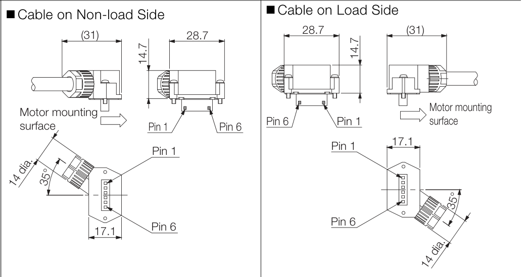
Yaskawa cable mating-face drawing for JZSP-C7M9-2-E / JST J27S (200-600 W SGMXJ, Sigma-7-compatible specification). Source: SIEPS80000132J, p. 3-6; Sigma-X selection confirmed by SIEPC71081212K, section 2.3.1.
| Pin | Signal | Typical Yaskawa cable color |
|---|---|---|
| 1 | FG / protective earth | Green/yellow |
| 2 | W | Blue |
| 3 | V | White |
| 4 | U | Red |
| 5 | Brake | Black |
| 6 | Brake | Black |
At the motor-end cable: With the motor disconnected and a verified connector identification, pins 5 and 6 are the brake feed/return pair. For a powered voltage check use a suitable breakout; for an ohmmeter test isolate all supplies and both cable ends.
Orientation limit: This JST drawing is a cable mating-face view, not a top-down motor-socket photo. Standard Sigma-X TE connectors use another housing: TE 2352404-1 for the small group. The numerical assignment does not authorize using the JST shell picture to locate a contact in a TE housing. Obtain the matching drawing from SIEPC71081212 section 2.3.1 and confirm molded numbers. A straight-on motor/cable photo is needed before annotating the original shop motor itself.
SGMXG small combined connector
Applies to: SGMXG-03/05 in the 200 V group, and SGMXG-05 in the 400 V group. The integrated connector includes PE plus five numbered contacts. The brake pair is 4 and 5, not 5 and 6.
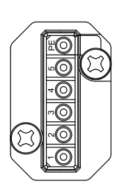
Manufacturer motor receptacle face. Source: SIEPC23021000H, p. 178 (200 V) and p. 197 (400 V).
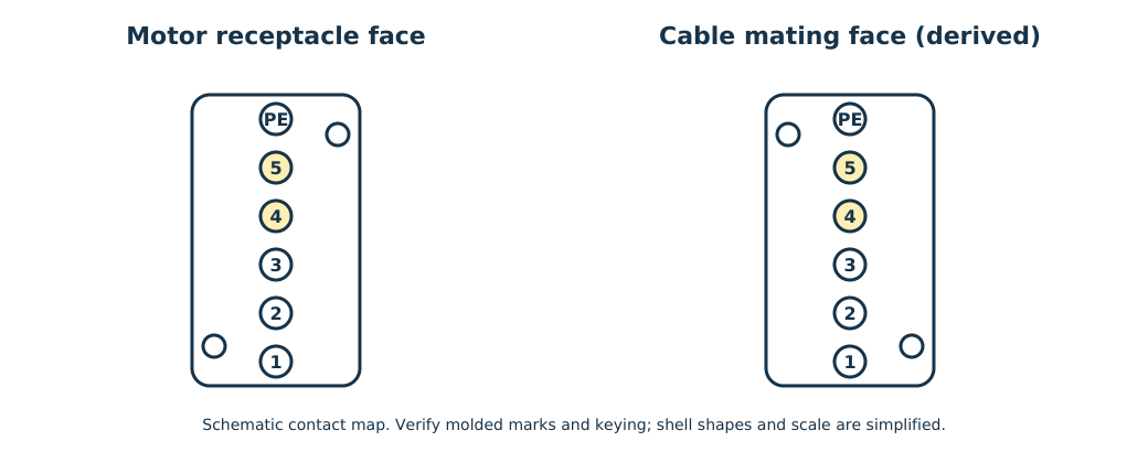
Derived contact maps: with the same vertical reference, the screw landmarks reverse on the cable mating counterpart.
| Contact | Function |
|---|---|
| PE | Frame ground |
| 1 | W phase |
| 2 | V phase |
| 3 | U phase |
| 4 and 5 | Holding brake |
Use the upper PE mark and the staggered mounting-screw positions as orientation landmarks. Never treat a six-contact housing as proof that it shares the small SGMXJ assignment. Follow the motor label and connector drawing together.
Larger motors: separate brake plug
Applies to: the listed SGMXA-15 through -50 and larger SGMXG groups with a separate two-contact brake receptacle. The main power plug and the brake plug are separate circuits. Verify the full output/speed/voltage variant in the motor manual.
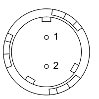
Manufacturer two-contact motor brake receptacle. Source: SIEPC23021000H, p. 102; larger G-family brake receptacles are shown on pp. 182, 188, 192, 201, 206 and 210.
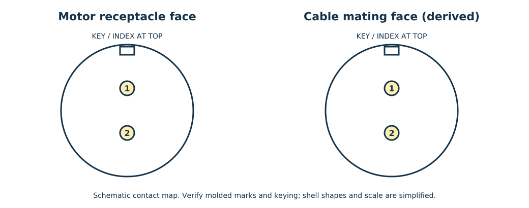
Derived two-contact mating map. Keep the index at the top; contacts 1 and 2 are the brake pair.
| Connector | Contacts |
|---|---|
| Brake plug | 1 and 2: brake coil; no voltage polarity at bare brake terminals |
| Main motor power | A U, B V, C W, D FG in the cited groups |
| Encoder | A separate signal connector; do not use as a brake test point |
A motor-end voltage test is made on the brake plug, not on the four-contact main power plug. For resistance diagnosis, separate the brake cable from the motor so the cable, coil and external suppression can be tested independently. No encoder disassembly is needed.
SGMXP 400 V round combined plug
Applies to: SGMXP-02/04/08/15, 400 V specification with the cited round main-circuit connector. Do not substitute the 200 V SGMXP rectangular-connector assignment.
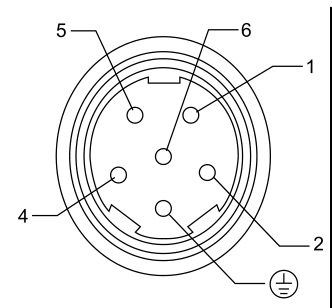
Manufacturer motor connector face. Source: SIEPC23021000H, p. 140 and p. 143.
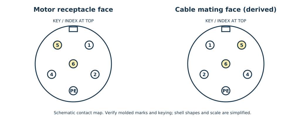
Derived mating contact map. Brake contacts 5 and 6 are highlighted; cable-side lateral positions reverse.
| Contact | Function |
|---|---|
| 1 | U phase |
| 2 | V phase |
| 4 | W phase |
| 5 and 6 | Holding brake |
| PE / connector case | Frame ground as specified by the manufacturer |
The motor power class is 400 V; this is not permission to apply 400 V to the brake. Confirm the actual motor brake rating before any supply test. Keep the key/index at the shown position and confirm molded contact identity.
SGMXJ brake-coil reference at 20 C
| Model group (200 V) | Nominal resistance | Range at +/-10% |
|---|---|---|
| A5 / 01 / C2 | 104.8 ohms | 94.32-115.28 ohms |
| 02 / 04 | 96 ohms | 86.4-105.6 ohms |
| 06 / 08 | 88.6 ohms | 79.74-97.46 ohms |
Correction: The earlier November 4 SGMXJ-06 handout used 96 ohms. That was a column-reading error. Use 88.6 ohms +/-10% at 20 C for the 06/08 group. Other families require their own specifications. Coil temperature and cable resistance affect a reading; a reading in range alone does not prove mechanical release.
What the shop troubleshooting established
Three relay indicators and 24 V at the panel were reported. Actual motor-end voltage under load, brake-coil resistance, axis mapping and timing were not established in the conversation. New relays and relocated diodes were candidates to inspect, not proven root causes. No final fault or successful repair was documented.
Replace these shortcuts with measured evidence: relay light = contact works; voltage at a terminal = the return path is good; 24 V at the panel = the motor cable is bad; all relays on = axis mapping and timing are correct; two black brake leads = all suppression is non-polarized.
Record the result before closing the job
Record motor/drive/cable model, drawing revision, coil voltage, contact drop, connected motor-end brake voltage, isolated motor resistance and temperature, cable continuity/isolation, drive-to-relay-to-motor mapping, release/application behavior, root cause, correction and final functional checks. Restore all guards and normal wiring. Retest safe holding and sequencing before returning the machine to service.
Source register and coverage notes
1. MachMotion: Brake Wiring for Yaskawa and drawing D0004 (legacy interface/relay example).
2. Yaskawa SIEPC23021000H: p. 56 resistance; pp. 102/114/118 separate A brake; pp. 140/143 P 400 V; pp. 178/197 small G; pp. 182-210 larger G.
3. Yaskawa SIEPC71081212K: main-circuit cables and connector kits, including standard vs compatible variants.
4. Yaskawa SIEPS80000132J, p. 3-6: JST connector-face illustration.
5. Yaskawa AN.SIGMA.01: holding-brake timing guidance; apply only to its stated models.
6. Live Odoo product catalog checked November 11, 2026. Catalog presence is not installed-machine verification.
Coverage note: Standard small TE connector-face artwork and straight-on photos of the original shop motor socket remain to be added. Use the matching manufacturer drawing and molded contact numbers; the JST housing picture is not a substitute for a TE housing drawing.