MachPro Spindle Configure for M31 up to Rev 1.2
Analog 0-10V and sinking outputs for spindle control
M31 Motion Controllers prior to Rev 1.3 use sinking outputs to control the CW and CCW direction of rotation on the spindle.
Using 0-10VDC to control the speed, and sinking outputs to control the rotation direction of the spindle
| **M31 Spindle features** | |
| Opto-Isolator Outputs | Forward and Reverse Open Drain / Open Collector outputs |
| Analog Speed Signal | 0-10VDC |
| Encoder Feedback | Yes |
M31 to VFD Direction Control – Field Wiring Guide
This section explains how to wire the M31 motion controller to a VFD (Variable Frequency Drive) for Forward and Reverse control.
The language here uses standard sinking and sourcing terms used by field technicians.
Key facts about the M31 outputs
- The M31 always uses sinking outputs.
- The Forward and Reverse outputs are optocoupled.
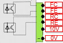
- Each output has an NPN sinking optocoupler to 0 V COM.
- When an output turns ON, it connects the VFD input to 0 V COM and sinks current.
- When an output turns OFF, the circuit is open and no current flows.
Sinking vs sourcing – basic idea
- A sourcing device provides +24 VDC to the circuit.
- A sinking device connects the circuit to 0 V COM to let current flow.
- The M31 is a sinking device.
- The VFD digital inputs usually act as sourcing inputs when configured for sinking-mode wiring.
What the VFD actually senses
- The VFD digital inputs sense current, not the 24 VDC level.
- The 24 VDC from the VFD is only a power source for the input circuit.
- The VFD decides ON or OFF by checking whether current flows into the digital input.
- If current flows, the input is active (Forward or Reverse commanded).
- If no current flows, the input is inactive (no command).
How VFD digital inputs should be configured
Most VFDs allow different wiring modes for digital inputs.
For use with the M31:
-
Configure the VFD digital inputs for sinking-type wiring.
-
In manuals, look for terms like:
- “Sink input”
- “NPN input”
- “Sinking (NPN) logic”
- “0 V common for digital inputs”
- “Digital inputs referenced to 0 V”
Avoid modes described as:
- “Source input”
- “PNP input”
- “24 V common for digital inputs” (where inputs switch to +24 V)
These modes are intended for sourcing outputs, not the M31.
Role of the VFD’s 24 VDC control supply
- The VFD normally provides a 24 VDC control supply terminal.
- The VFD routes this 24 VDC to each digital input circuit.
- The 24 VDC exists only to allow current to flow through the input and the M31 output.
- The VFD’s decision is based on current presence, not on “seeing 24 VDC”.
Forward and Reverse OFF (no command)
When both M31 Forward and M31 Reverse outputs are OFF:
-
Both optocoupled outputs are open circuits.
-
No current flows from the VFD’s 24 VDC supply through the Forward input.
-
No current flows through the Reverse input.
-
The VFD reads:
- Forward input = OFF
- Reverse input = OFF
-
The VFD sees no direction command.
Forward ON – sinking current
When the M31 Forward output turns ON:
- The VFD supplies 24 VDC to the Forward digital input circuit.
- The VFD Forward digital input connects to the M31’s Forward Collector (FC).
- The M31 closes the path between collector and emitter in the Forward output.
- The emitter connects to 0 V COM.
- Current flows:
VFD 24 VDC → M31 Forward Collector (FC)→ M31 Forward emitter (FE) → 0 V COM - The M31 is sinking this current.
- The VFD senses this current flow and interprets it as Forward = ON.
Reverse ON – sinking current
When the M31 Reverse output turns ON:
- The VFD supplies 24 VDC to the Reverse digital input circuit.
- The VFD Reverse digital input connects to the M31’s Reverse collector (RC).
- The M31 closes the path between collector and emitter in the Reverse output.
- The emitter connects to 0 V COM.
- Current flows:
VFD 24 VDC → M31 Reverse Collecter (RC)→ M31 Reverse emitter (RE) → 0 V COM - The M31 is sinking this current.
- The VFD senses this current flow and interprets it as Reverse = ON.
Wiring checklist for field technicians
When wiring a VFD to the M31:
-
Find in the VFD manual:
- 24 VDC control supply terminal.
- 0 V COM (or “DC-”, “CM”, “COM”) terminal.
- Digital input terminals for Forward / Run and Reverse.
- Digital input mode settings related to sink / source / NPN / PNP.
-
Configure the VFD digital inputs for:
- Sink / NPN / sinking logic mode.
- Inputs referenced to 0 V COM.
-
Wire the control supply and commons:
- Connect VFD 0 V COM to M31 FE and RE.
- Use the VFD’s 24 VDC as the field control supply for its inputs.
-
Wire the direction signals:
- Connect the VFD Forward input to the M31 Forward collector (FC) terminal.
- Connect the VFD Reverse input to the M31 Reverse collector (RC) terminal.
-
Verify operation:
- Command Forward from the M31 and confirm the VFD sees Forward ON.
- Command Reverse from the M31 and confirm the VFD sees Reverse ON.
Summary
- The M31 always uses sinking outputs for Forward and Reverse.
- The VFD senses current, not 24 VDC level.
- Set VFD digital inputs to sink / NPN / sinking logic mode.
- The VFD sources 24 VDC, and the M31 sinks current to 0 V COM to signal direction.

For 0-10VDC speed control, look for Analog Inputs (AI) and 0VDC connections on the VFD.
| Analog Inputs: AI1, V1, AVI | 0 volt: AC, 0V, ACM, GND |
For direction control look for, or configure the Forward and Reverse digital control inputs on the VFD. This will also need a 0VDC connection.
| Digital Inputs: S1, FWD, S2, REV, | 0 volt: SN, SC, DCM |
This is an example connecting the M31 to a Yaskawa GA500 VFD. Please refer to the documentation for your VFD.
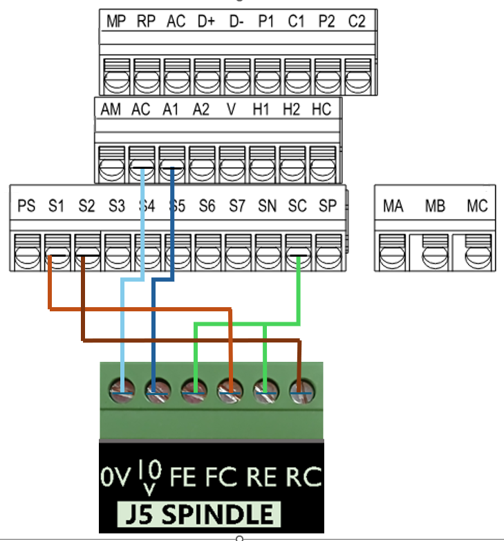
| **M31 Motion Control** | **Yaskawa GA500 VFD** |
| 0-10VDC speed control | A1 |
| 0VDC | AC |
| Forward Collector (sinking) | S1 (forward by default) |
| Reverse Collector (sinking) | S2 (reverse by default) |
| Forward Emitter | SC (common) |
| Reverse Emitter | SC (common) |
Here is a diagram showing the electronic circuit of the M31 on the Emitter and Collector signals: