
SOURCE PRIVATE MachPro Required Configuration Settings
Required is probably not the right word. These are settings that will generally need to be made by everyone configuring a new MachPro system - regardless of machine type.
Which materials need to be in operator rather than setup?
try to distinguish between these types and probably arrange the content in this order:
| Type | User question | Main purpose | What it contains | What to avoid |
|---|---|---|---|---|
| Tutorial | “How do I learn this?” | Teach skills through guided practice | A safe, step-by-step lesson with a small success | Long explanations, options, “choose your own path” diataxis.fr+1 |
| How-to guide | “How do I do this task?” | Help a competent user finish a goal | A focused set of actions to achieve a result | Teaching, background, full reference dumps diataxis.fr+1 |
| Reference | “What are the exact details?” | Provide correct facts for lookup | Neutral, structured description (often API docs) | Opinion, discussion, step-by-step “recipes” diataxis.fr+1 |
| Explanation | “Why does this work this way?” | Build understanding and context | Concepts, rationale, tradeoffs, design reasons | Procedural instructions, reference-style listings diataxis.fr+1 |
M31 Emergency Stop Input Mapping
-
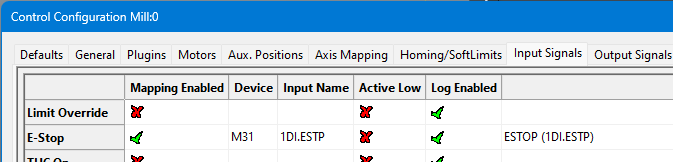
The Emergency Stop input is mapped to
M31[motion controller] 1DI.ESTP. -
When configured correctly, opening the E-Stop terminals will disable the system.
-
The system will only operate when the E-Stop circuit is closed and healthy.
Hardware and drive enable overview (J12)
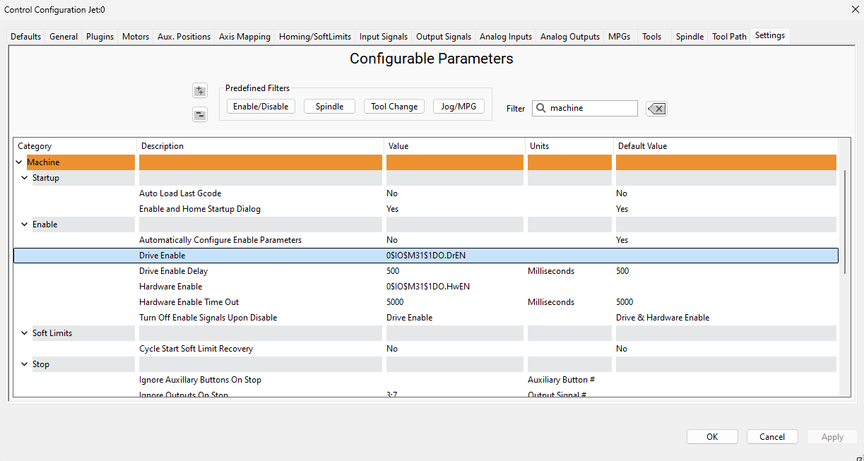
Before you use hardware enable or drive enable, configure the emergency stop circuit.
The M31 includes two control circuits: hardware enable and drive enable.These circuits remain inactive until you configure the emergency stop (E-stop) circuit.
Use the default settings unless your application requires changes.
Accessing the enable settings
-
Open Configure > Control.
-
Select the Settings tab.
Available options
In the Settings tab, you can:
-
Set the delay between hardware enable and drive enable.
-
Choose which outputs turn off when the system disables.
Configure thea Dedicated Network Interface (J20)to the motion controller
The M31 motion controller connects to the control computer through a static IP Ethernet connection.
Follow the Microsoft guide below to manually set your network adapter to communicate with the M31:motion controller:
Microsoft Instructions: Manually Configure IPv4 Settings Scroll to the bottom and expand the section titled “To specify IPv4 settings manually.”
Then perform the following steps:
-
Set IP address to:
192.168.208.10 -
Set Subnet mask to:
255.255.255.0 -
Save the settings and close the window.
-
Connect the Mach J20 port to the dedicated network port on the control computer.
The M31 IP address (192.168.208.35) and the computer adapter IP (192.168.208.10) are pre-configured and should never be changed.
After double clicking on your MachPro shortcut, a window will come up asking to Press Cycle Start to Enable Mach and Home All Axes . By default on a new installation, MachPro will just home in place.place. Press [Cycle Start] and the control will enable and home all axes.

This prompt can be turned off in the MachPro settings if desired.
The configuration menus are locked if the system is enabled, and all the menu options will be grayed out. You need to disable the system in order to make configuration changes.
If using step and direction, wire up your drives to J13-J18.
Connect to a single-ended drive input
Use this when
The controller hastrue differential (RS-422)step/dir outputs, andThe drive hassingle-endedstep/dir inputs.
Connections
ConnectS+→ driveSTEPinput.Drive label examples: “PUL”, “STEP”, “CP”.ConnectD+→ driveDIRinput.Drive label examples: “DIR”, “CW/CCW”.Connect controller0 V→ drive input common / signal ground.Drive label examples: “PUL-”, “DIR-”, “COM”, “GND”, “SG”, “DCM”.
Do not connect
LeaveS-andD-unconnected.
Why
On many controllers, S- and D- are the inverted, actively driven outputs of the differential pair. If you tie them to 0 V, you can short an output or distort the signal. This can cause missed steps or faults.
Connect to a differential (RS-422) drive input
Use this when
The controller hastrue differential (RS-422)step/dir outputs, andThe drive hasdifferentialstep/dir inputs.
Connections (typical)
ConnectS+→ driveSTEP+input.Drive label examples: “PUL+”, “STEP+”, “CP+”.ConnectS-→ driveSTEP-input.Drive label examples: “PUL-”, “STEP-”, “CP-”.ConnectD+→ driveDIR+input.Drive label examples: “DIR+”, “CW+”.ConnectD-→ driveDIR-input.Drive label examples: “DIR-”, “CW-”, “CCW-”.
0 V connection
In most differential interfaces, a separate0 Vwire is not required for the signal to work, because the receiver measures the voltage difference between “+” and “-”.If the drive manual specifies asignal ground,shield drain, orCOMconnection for noise control, connect it as specified.If the drive manual does not require a 0V connection, then do not connect it.Do not useS-orD-as a ground.
Notes
Use twisted pairs:S+ with S-, andD+ with D-.If you use cable shield, bond it per your grounding standard and the drive manual (usually at one end).
EtherCat Connection and Configuration (J19)
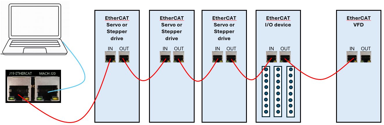
The M31 uses a standard EtherCat physical connection plan. The computer connects via Ethernet to J20 on the M31 motion controller. J19 on the M31 is then used to connect to each of the EtherCat devices.
-
Put servo & stepper drives first in the EtherCAT chain (closest to the controller).
-
Put I/O devices and safety relays in the middle.
-
Put VFDs last (at the end of the chain). VFDs make electrical noise — keeping them last lowers interference.
-
Use shielded network cable for all EtherCAT devices.
-
Cable length: keep each cable between 1 foot and 100 meters (about 0.3 m – 100 m).
-
Good cable management: keep cables neat, do not bend them sharply, and separate network cables from high-power lines when possible.
Enabling Axes
After the drives are connected to the M31,motion controller, open up MachPro, and enable the axes as follows:
Note: This may already be setup depending on your system.
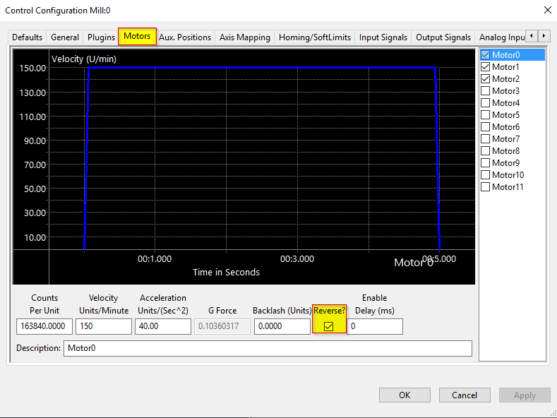
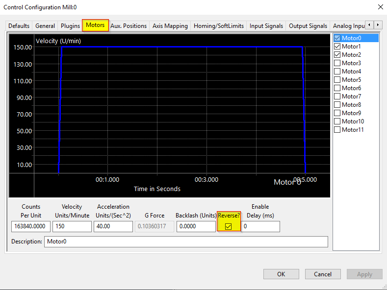
- Enable all the motors that are to be controlled by setting the respective boxes in the right pane to checks. In the example below, motors 0, 1, and 2 are enabled.
- If a motor moves the wrong direction, it can be reversed in the MachPro. Check the Reverse? box if the motor direction needs to be reversed. The motor will now move the opposite direction than it did before. If the homing direction was already set, it will need to be reversed as well. (see the homing section ). NOTE:
If you are needing to reverse direction on an axisAxes witha slave motor, you may need to change the direction for both themaster and slaveaxis.motors typically need to have one motor reversed, and the other left to run normally. - Press [ Apply ] to save any changes.
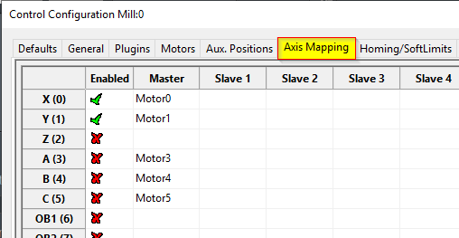
- Next, select the Axis Mapping tab as pictured below. Associate the enabled motors to the applicable axis. In this example, Motor0 is the X master, Motor1 is the Y master, and Motor2 is not mapped to an axis.
In this EtherCat system the VFD and spindle are motor 2, but will not be used for axis movement.No slave axes are configured on this system.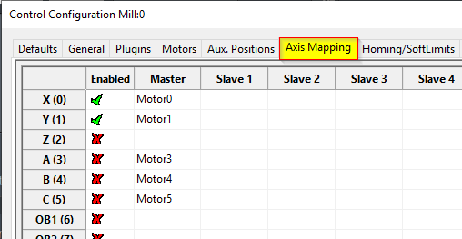
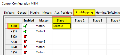
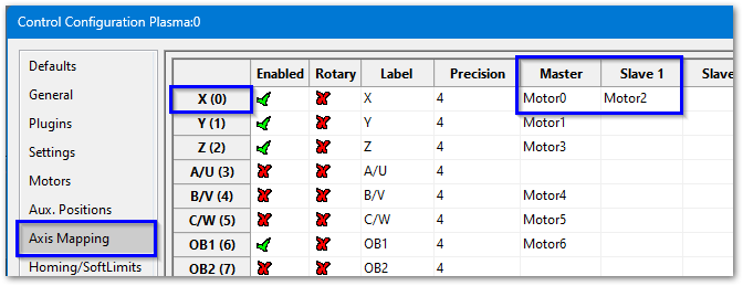
- If you have an axis with two motors - such as a gantry - one motor will be the master and the second will be the slave. In the slave column, select the motor that will be running in slave mode. In this example X axis has Motor0 as the master and Motor2 as the slave.
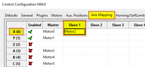
- Press [ Apply ] and [ OK ] to save and close.
- Carefully test jogging. If you have a gantry with two motors, you may need to reverse one motor for correct motion. See step 2 above.
The system should now be able to jog, however,....
WARNING
The machine can be crashed very easily at this point. The axes need to be calibrated and the limits set up now.
Axis Calibration
Before calibrating the axes,axes setremove theall backlash unitssettings to 0 forfrom each axis. See the Backlash Repair and Compensation section below for details.
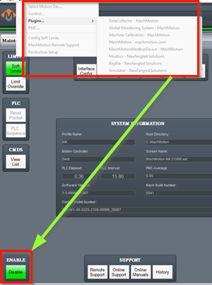
Go to Configure-> Plugins -> Machine Calibration.
Select the type of configuration you would like to perform from the window:
- Manual - Calculate the axes by comparing distance traveled vs. distance commanded. See Manual Calibration below for instructions.
- Automatic - Calibrate axes using the specifications of your system. Continue for instructions.
Automatic Units Calibration
Automatic calibration requires you to provide all of the details of your motor and axis hardware. If you are unable to find this information, proceed to the Manual Calibration section.
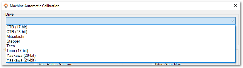
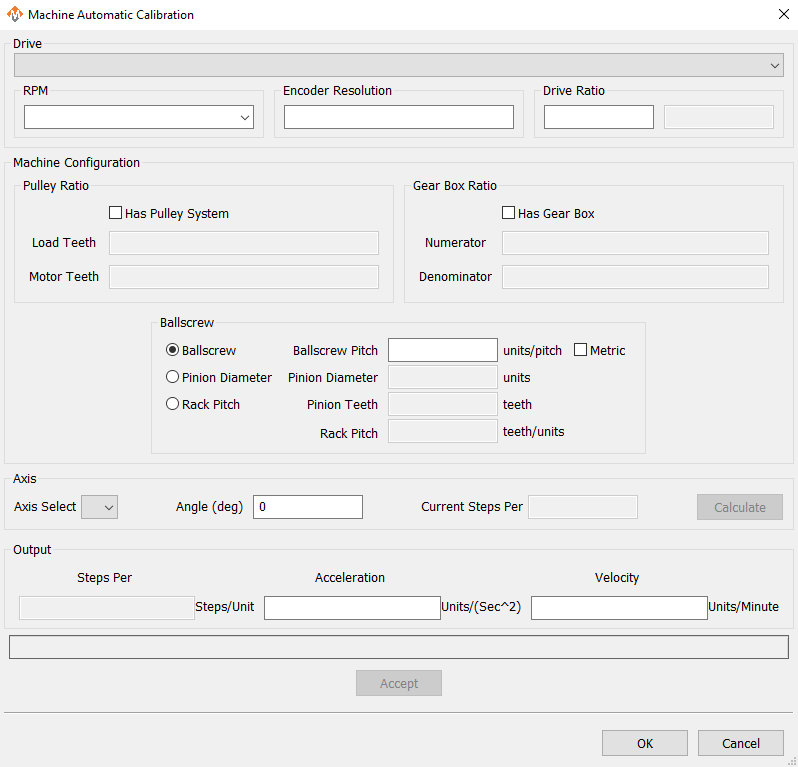
- Select the Drive that most closely matches yours. If there is not an exact match, select based on the number of encoder resolution bits.
- Select the max motor RPM
- Enter 131,072 for the Encoder Resolution. If you have a stepper drive, or the drive is less than 17 bit, then enter the actual resolution per rotation for your motor.
To verify the actual encoder resolution of your drive, please use the steps above inChecking Resolution. - Enter 1 for the drive ratio.
- If this axis uses a pulley, select that box and enter the number of teeth from the load side and the motor side.
- If there is a gearbox, select that box and enter the ratio.
- This axis will have either a ballscrew or rack and pinion system. Select the type it has and complete the open fields.
- Select the axis to calibrate.
- Leave Angle at 0 degrees
- Press the [Calculate] button.
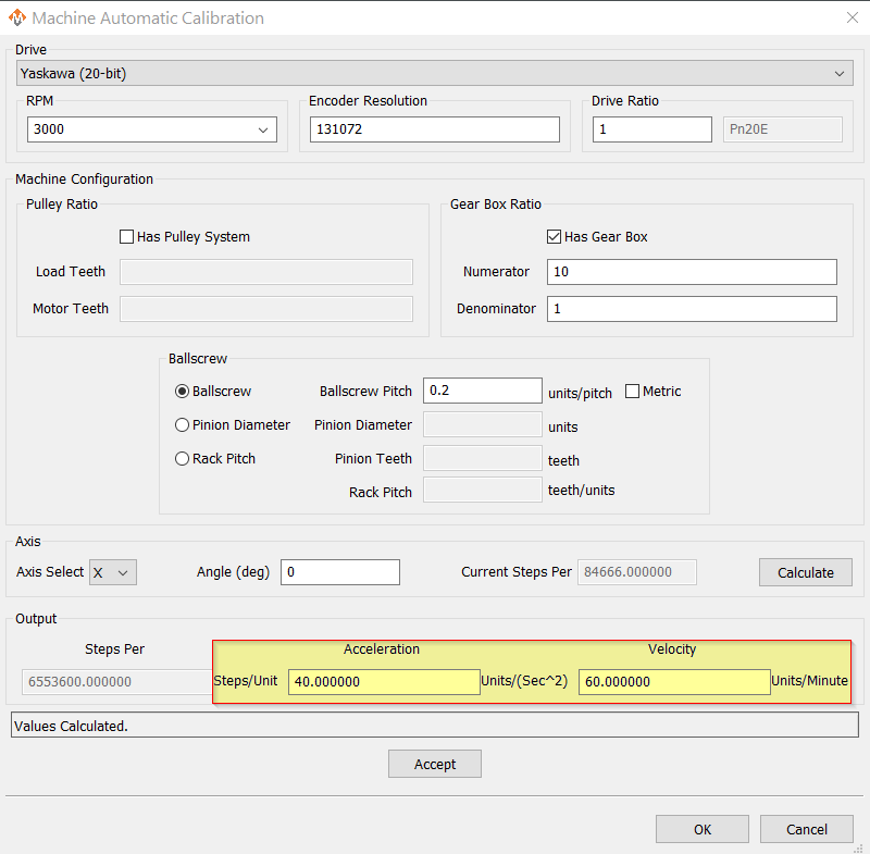
- Evaluate the current steps value against the proposed values. You may change values and re-calculate.
- When you are ready to Accept the new steps per value, enter in the maximum Acceleration and Velocity values that you want for this axis.
Repeat for each axis.
Press [OK] and restart MachPro to save the calibration settings.
This is an example of a simple X axis that has been calculated and is ready to be accepted. You may need to change the Acceleration and Velocity values to be appropriate for your machine.
Verify that each axis is moving the distance that you command.
Manual Calibration
This tool will enable you to calibrate your axes based on measuring actual distances moved and updating the MachPro parameters. Use the longest distance that you can accurately measure to calibrate each axis.
You will be commanding motion on each axis. Carefully jog each axis to the middle of travel before starting calibration.
- Select the axis to calibrate.
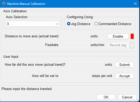
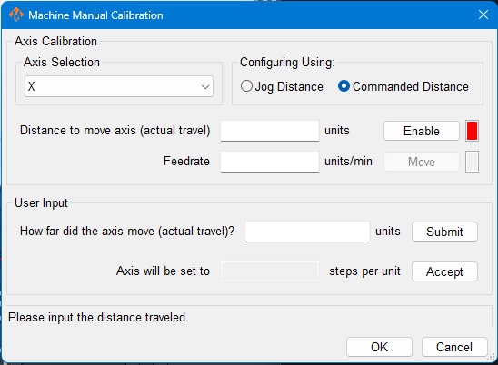
- Select either Jog Distance or Commanded Distance. Jogging allows you to directly control the speed and distance the axis moves.
|
Manual Calibration Using Jogged Distance |
Manual Calibration Using Commanded Distance |
|---|---|
|
|
|
|
|
|
Pressing [ Accept ] at this point will update the steps per unit on this axis
|
Pressing [ Accept ] at this point will update the steps per unit on this axis |
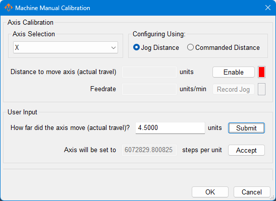
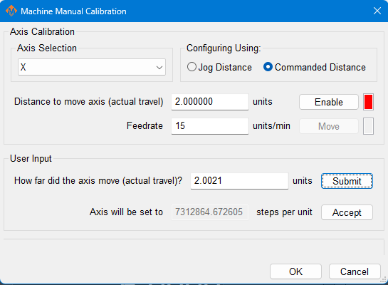
Axis calibration is a core function of a CNC control. Ensure that it now meets your accuracy requirements before moving on in the configuration. All of the following configuration steps depend on calibration, and if you later change the calibration, you will need to reconfigure many of the items below.
Configure Velocity and Acceleration
If you want to adjust your velocity, select Configure on the top menu bar, then Control . Select the Motors tab as shown below.
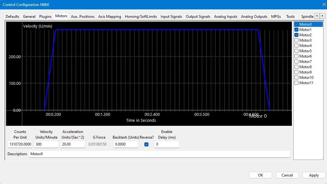 In the right pane, click on the motor you want to set up.
Click the word to highlight and select the axis. The checkbox is for enabling/disabling the motor
The selected motor’s parameters will be loaded and the velocity or acceleration settings can be adjusted.
- The max velocity is limited by several factors, including the motor. If you want an axis rapid speed to be limited or lowered, adjust the velocity for that motor to the max speed you want the rapid to be. The rigidity of the machine hardware will limit practical maximum velocity of an axis. The cut quality and accuracy will degrade as it reaches that point.
- For stepper motors, max acceleration is typically 15-20 if in standard units. For servo motors, start with value of 30-40. This parameter also sets the deceleration rate, which interacts with a regeneration resistor - if one is installed on this axis.
Press [ Apply ] before clicking on another motor or closing out the Mach Configuration window. NOTE: If you change the counts per unit, the velocity and acceleration values will adjust accordingly. If you do not want them to change, type in the current values shown. Verify by clicking another motor and then coming back to the adjusted motor.
WARNING
No limits have been set up. DEATH, INJURY or serious PROPERTY DAMAGE can occur if the system is not operated carefully. Limits and homing setup will be completed in section 3
Backlash Repair and Compensation
Backlash is caused by the gaps between moving parts such as gears and ballscrews. It is the amount of movement one component can make in one direction without causing motion in the next connected part. Most mechanical systems have some backlash - even when new. If the mechanics are too tight, binding and excessive wear will result. As the gears and ballscrews wear, the backlash will increase, and accuracy will decrease. Ongoing testing and maintenance of your mechanical system is required to minimize backlash.
All of the axes are now calibrated, but MachPro does not know where the limits of travel are on each axis. That will be configured next. Until that setup is completed, be very careful if you are moving axes.
Note: For the highest level of safety, wire the limit switches Normally Closed. If a limit is tripped, or a wire or limit is damaged, the system will stop motion.
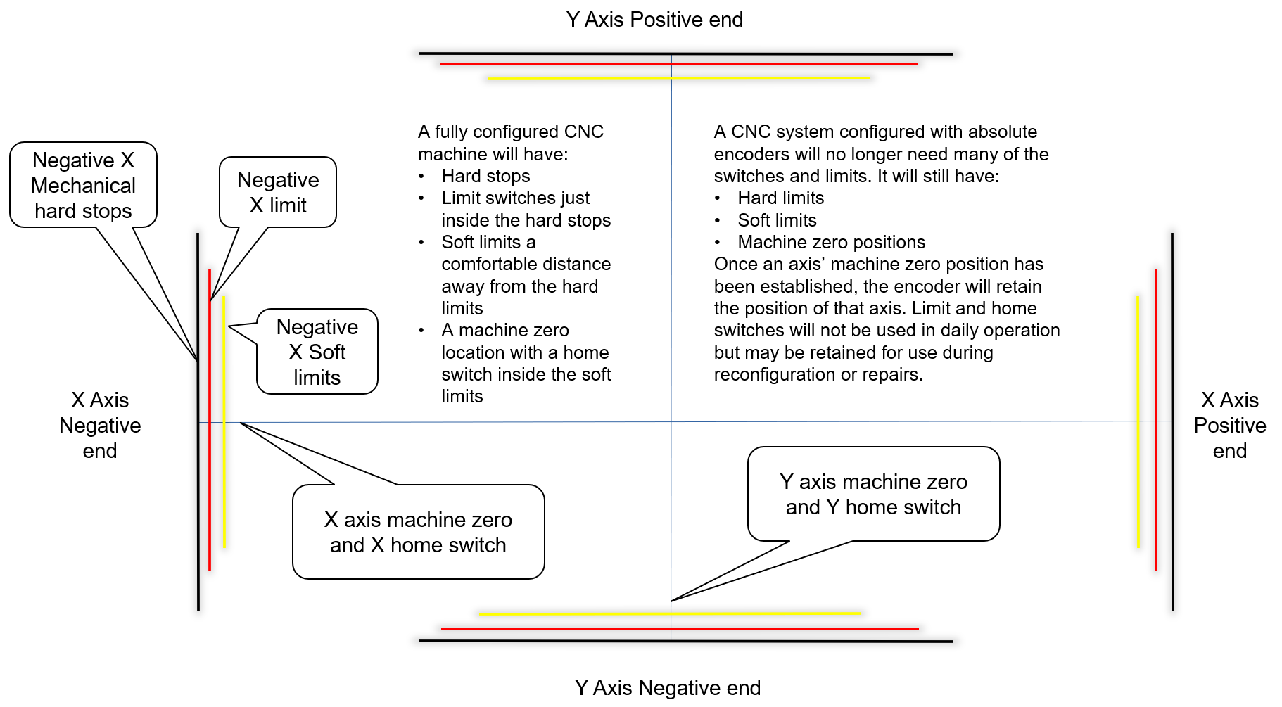
To wire 24V limit switches, follow the steps outlined below.
-
- Select, or install, two limit switches at the end of each axis' hard limits.
- Wire the two switches in series, normally closed. If either limit is tripped, the circuit will open and motion will stop.
- I/O ports are limited, and wiring the limits for a given axis in series conserves those limited ports while maintaining function.
Note that safety circuits often require each limit to have its own input.
Wire one side of the first switch to +24V from the M31 motion controller.Wire the other side of the limit switch into an input on the M31. Label the wires and document the I/O.
Wire a home switch on each axis to a separate input.
Tip for success: Once you understand how to wire and map inputs and outputs, complete the charts in the appendix at the end of this document.
Mapping Signals
Short example
-
Motor 0: Home, ++, and -- are enabled (green check).
-
All limits are wired normally closed.
-
We
useused M31 1DI.01.09 for both ++ and --. -
We
useused M31 1DI.01.08 for the Home switch. Using a separate input for Home is more reliable.
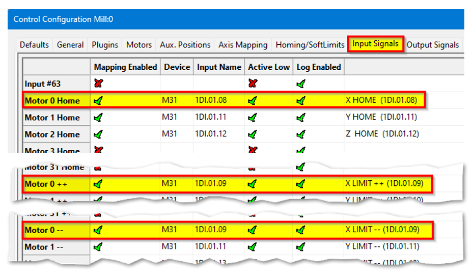
Manually trigger each limit switch and make sure they disable Mach before continuing. This verifies both the wiring and signal mapping.
Homing Setup
-
Danger: If limit switches are wrong or an axis moves the wrong way, the machine can crash.
-
Do this first: Keep your hand on the Emergency Stop button the first time you run homing.
-
Open the settings: From the menu bar click Configure → Control. Then click the Homing/SoftLimits tab.

-
Home Dir: Pick the direction the axis will move to find home — positive or negative.
-
Home Order: Set the order of homing using numbers (1 = first, 2 = second, etc.).
-
Tip: Z is often set to 1 so it moves up first and stays out of the way.
-
-
Home Speed%: Set how fast the axis homes by choosing a percent.
-
20% is the usual maximum for best results.
-
Slower speeds help stop over-travel.
-
You can jog (move) the axis quickly close to the home position before homing to save time.
-
-
Home In Place: Set this based on your hardware in the
controllerM31motionconfig:- config.
- This
Ifisyouusedusewithhome switcheswired through M31 → make sureHome In Placeshows ared X. If you useabsoluteencodersencoderin M31 → make sureHome In Placeshows agreen ✓.systems.
- This
-
Save: Press OK to save your changes.
-
Test: Home each axis one by one to check the settings. Then press Home All to verify everything works.
Homing Slave Axis
There are 2 configuration options:
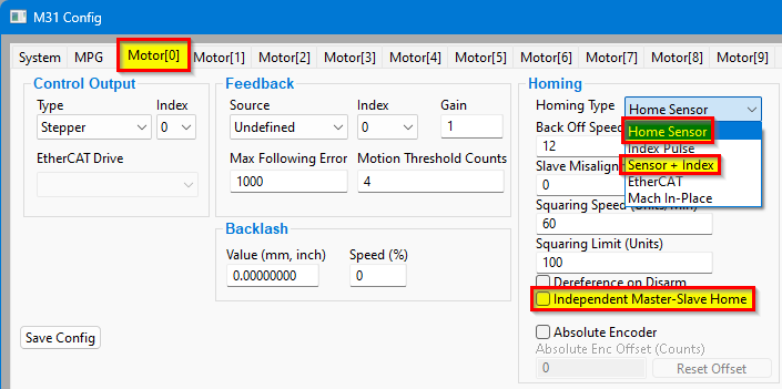
1. Homing with the home switch only on the MasterMaster. In this configuration, the slave axis will use the input signal from the master home switch. You will also need to configure the axes in the motion controller.
|
Open Configure → Control → Axis Mapping.
|
|
|
Open Configure → Control → Input Signals.
|
|
|
|


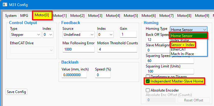
2. Homing with both Master and Slave having their own home sensorssensors. In this configuration, the master and slave axes each have their own home switch. This is the preferred configuration.
|
Open Configure → Control → Axis Mapping.
|
|
|
Open Configure → Control → Input Signals.
|
|
|
|

Set Slave Misalignment value if needed to "square" the gantry
https://support.machmotion.com/books/knowledge-base/page/aligning-slave-axis-gantry---mach4
Troubleshooting
- What happens: When you touch off switches and home, one side keeps moving and drags the other side. This is a sign the switch assignments are swapped.
-
What it means: The home switch used for the master may actually be wired to the slave (they are swapped).
What happens:When you touch off switches and home, one side keeps moving anddragsthe other side. This is a sign the switch assignments are swapped.-
How to check:
-
Touch each home switch by hand (one side at a time).
-
Home the machine and watch each side while you touch the switches.
-
If one side still travels and pulls the other side, the switch mapping is likely wrong.
-
-
What to check in software: Look at Input Signals and Axis Mapping to make sure each switch is assigned to the correct axis.
-
Safety: Keep your hand on E-Stop the first time you test after changes.
Soft Limits Setup
With machine homed correctly and soft limits set, the machine will not hit a physical limit switch. If at any time a command is made for the machine to move outside of the soft limits (while they are enabled), an error will appear in the status line and motion will stop. To set up the soft limits, follow the procedure outlined below.
- Home the machine.
- Select to view Machine Coordinates on the Locked screen view so that the DRO’s are orange.
-
- Jog the machine to the maximum safe distance from the homing switches.
- Note: Make sure to stay inside the physical limit switches. If the machine is jogged outside of the limit switches, it completely defeats the purpose of soft limits.
- Record the machine coordinates at the end of the travel for each axis.
- Jog the machine to the maximum safe distance beyond the homing switches, and record the machine coordinates for each axis.
- Open the menu bar and click Configure->Control and select the Homing/SoftLimits tab as previously shown.
- Enable soft limits on each desired axis by setting the Soft Enable column to a green check mark, and enter in the recorded values.
- For each axis, enter the largest, most positive value in the Soft Max field, and the smallest, most negative value in the Soft Min field.
- Press [ OK ] to save changes. Test the soft limits by jogging the axes to maximum amounts in all directions.

Note: When loading a G-code file, the tool path display will show the soft limits as dashed lines. If any part of the tool path renders outside the soft limits, check your file.
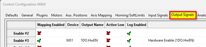
Mapping Signals to Outputs
To configure an output, follow the procedure below.
Using Outputs
Outputs 0-5 can be controlled with M-Codes. One M-Code turns an output on, and the other M-Code turns the output off. Use the table below for a reference.
|
Custom M-Codes |
Functions |
Default Output |
|
M200 |
Output 0 on |
DO-2 |
|
M201 |
Output 0 off |
|
|
M202 |
Output 1 on |
DO-3 |
|
M203 |
Output 1 off |
|
|
M204 |
Output 2 on |
DO-4 |
|
M205 |
Output 2 off |
|
|
M206 |
Output 3 on |
DO-5 |
|
M207 |
Output 3 off |
|
|
M208 |
Output 4 on |
DO-6 |
|
M209 |
Output 4 off |
|
|
M210 |
Output 5 on |
DO-7 |
|
M211 |
Output 5 off |
Mist and Flood Control
Mist is preconfigured in the MachPro software to be wired into Y0 and flood into Y1 output terminals.
|
Feature |
ON M-Code |
OFF M-Code |
Preconfigured Output |
|
Mist |
M7 |
M9 |
Mist On – 1DO.01.07 |
|
Flood |
M8 |
Coolant On – 1DO.01.06 |
5 Spindle Setup (J5)
Configure the VFD for the spindle motor
A VFD (Variable Frequency Drive) controls the speed of the spindle motor.
Set the VFD to match the motor’s electrical ratings:
-
Rated voltage
-
Rated current
-
Rated speed (RPM range)
You must use the values from:
-
The VFD manual
-
The spindle motor manual
Do not guess these values.
spindle calibration include
Explanation
Backlash Repair and Compensation
Backlash is caused by the gaps between moving parts such as gears and ballscrews. It is the amount of movement one component can make in one direction without causing motion in the next connected part. Most mechanical systems have some backlash - even when new. If the mechanics are too tight, binding and excessive wear will result. As the gears and ballscrews wear, the backlash will increase, and accuracy will decrease. Ongoing testing and maintenance of your mechanical system is required to minimize backlash.