
PRIVATE MachPro M31 Configuring a Master Slave Axis Gantry
This only applies to master and slave axes on a gantry. If you are trying to align the tables on a dual table router, use the home offsets in MachPro. Pull down Configure -> Control -> Homing / Soft Limits tab.
To align
Square the gantry,gantry mechanically
The gantry and table need to be mechanically squared to each other so that the gantry remains square to the table over the full length of its travel. This is also a good time to check all axes for backlash and do any needed maintenance to remove the backlash.
Configure the master and slave axesaxes.
- Pull
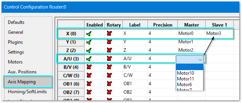
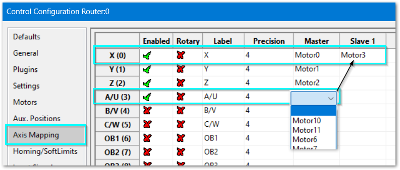
home,downthenConfigure -> Control -> and select Axis Mapping - On the axis that will be slaved, pull down the motor selector and select the top blank entry
- On the axis that will be the master, pull down the Slave 1 motor selector and select the motor that you just removed from your slaved axis.
-
- Close this window
When the gantry homes, the slave needsaxis can be set to move bya small offset to square the offsetgantry valueto youthe enter.table. There are two home sensor configurations that will work.
Pull down Configure -> Plugins -> M31
Both the master and slave motors need to havebe theconfigured Hometo Switchboxto selecteda sensor. The specific sensor mapping for each configuration is shown below.
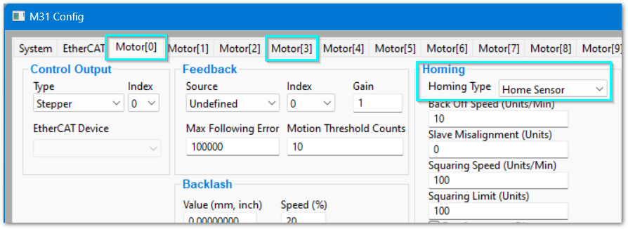
Home sensors on both configurations.
axes
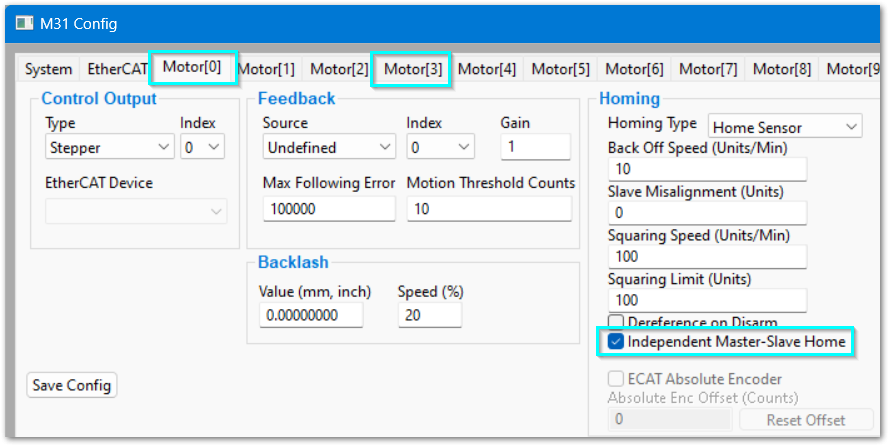
- If you have homing
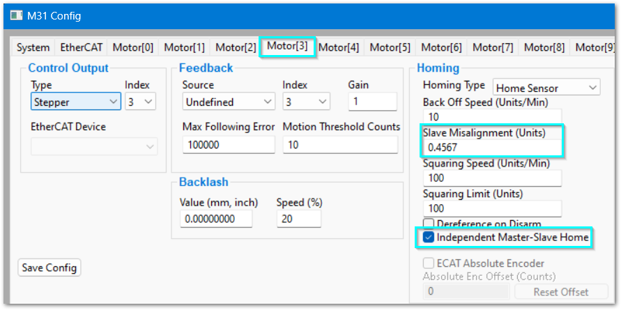
switchessensors on both the master and slave axis, then select theIndependent Master-Slave Homebox on both the master and slave motors. This tells the M31 that each motor will home to its own home sensor. - Close the M31 Config window.
- Configure each motor with its own input home sensor.
- Pull down Configure -> Control -> and select Input Signals
-
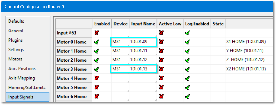
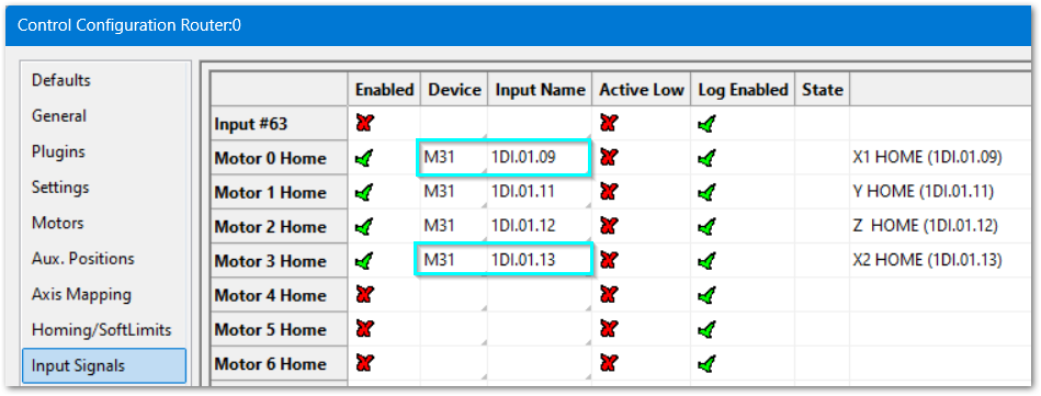
- In this example Motor 0 is homing to the sensor wired to M31 1D1.01.09. Motor 1 is homing to the sensor wired to to M31 1D1.01.13
- Verify that each home sensor triggers correctly so that the gantry will home correctly.
- Move down to the Gantry Alignment section
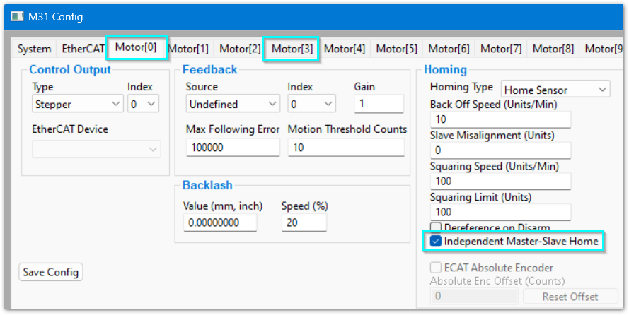
Home sensor only on the master axis
Pull down Configure -> Plugins -> M31
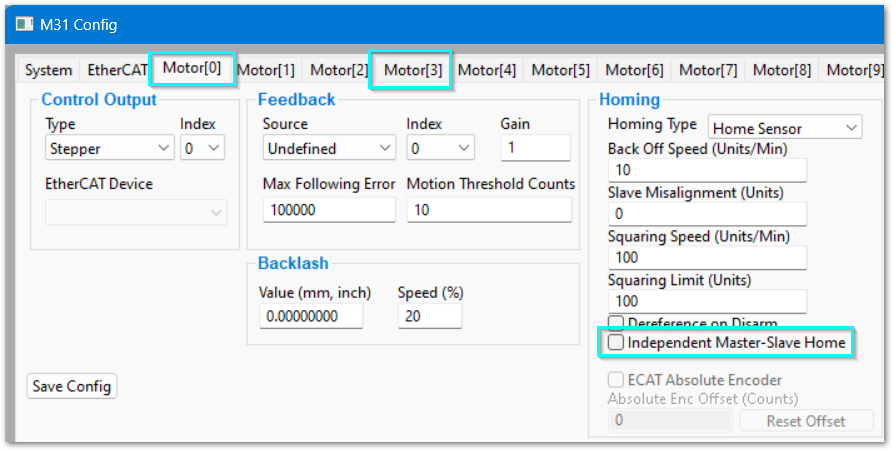
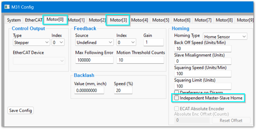
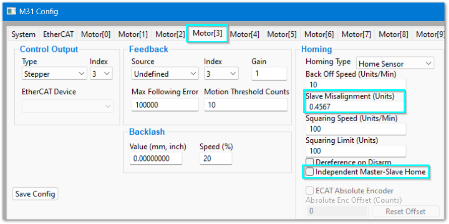
- If you only have one home sensor, on the master axis, then deselect the Independent Master-Slave Home box on both the master and slave motors. This tells the
HiCONM31 thateachbothmotoraxes will use the same home sensor. - Close the M31 Config window.
- Map the home sensors for both axes.
- Pull down Configure -> Control -> and select Input Signals
-
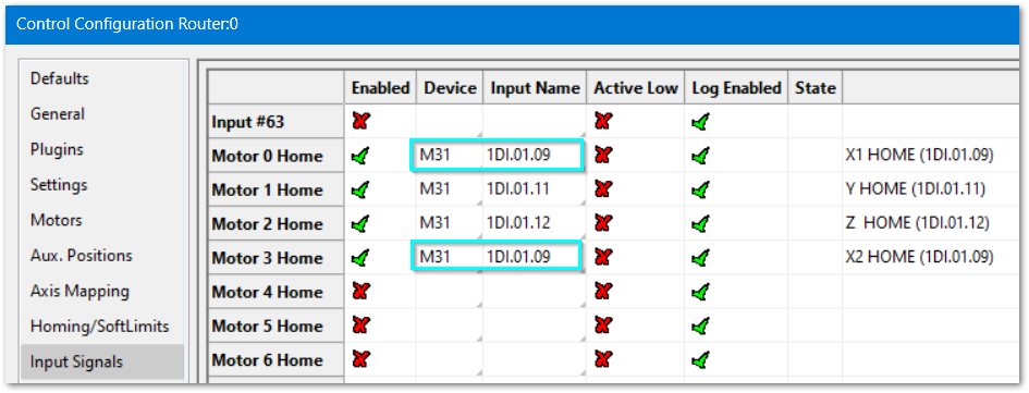
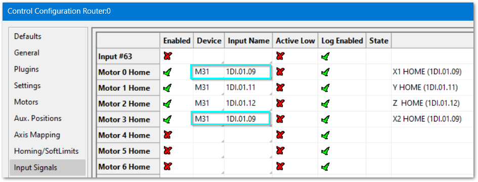
- In this example, both motors are mapped to
itsuseowntheswitch.same physical home sensor, which is wired to M31 1D1.01.09 - Verify that
eachthemotor has its own input, indicating separatesingle homeswitches.sensor triggers properly and the gantry homes correctly.
Configure gantry alignment
- This is one method among many and you are welcome to use other methods.
- Square the gantry mechanically first. The software method below will use motor torque to maintain squareness beyond what can be accomplished mechanically. There are limits to how much the motors can do.
- The wear on the racks or ball screws is not even across the whole unit. Typically there will be more wear in the middle. On an older machine, do the squaring process with the head in the central area of the table to achieve the best results.
- Typically one type of material is used when you need the most accuracy. Use scrap of that material for your testing. The materials need to be hard enough that you can accurately measure them with a set of calipers.
- Review the instructions for your calipers to obtain the most accurate measurements.
- Expect this job to take several hours
Measure the width of the table from rack/screw to rack/screw. That will typically be a whole number of feet. If you're squaring an imperial manufactured machine in a metric shop, continue to use metric measurements.
- Cut a square and measure corner to corner diagonally. Or, drill a 4-hole square pattern and measure corner-to-corner on that pattern.
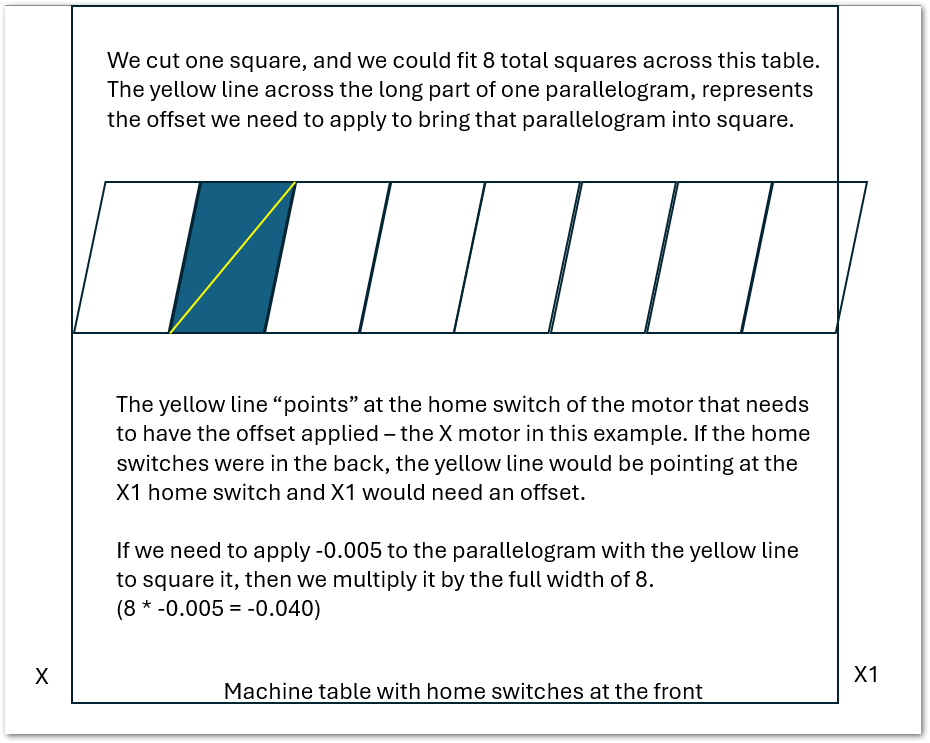
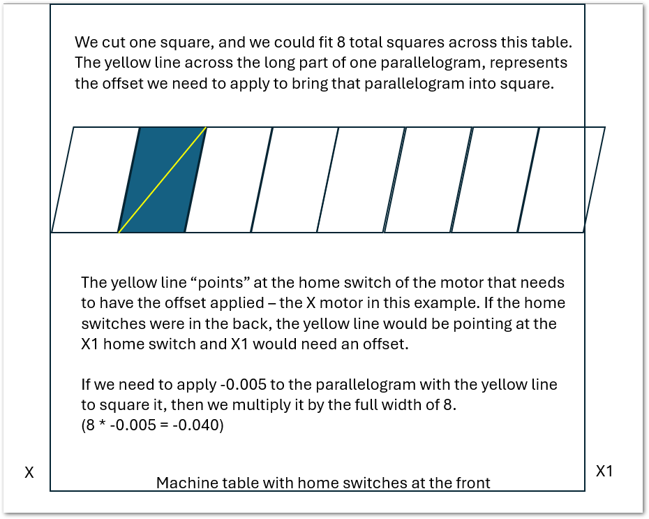
- The long diagonal line will point to the home sensor of the axis that needs to have offset added.
- Larger squares yield better results, but they need to be small enough to measure corner-to-corner diagonally with your calipers.
- Cut the squares away from the edge so that the material is held in place during the entire cut.
- Cut the lead-in and lead-out along one of the edges rather than at a corner
- Your square is likely a parallelogram - even slightly. The image below shows exaggerated parallelograms to clarify the problem to be solved.
|
|
|
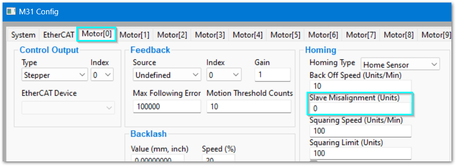
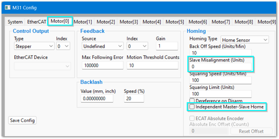
| The master motor Slave Misalignment value will always be set to 0. |
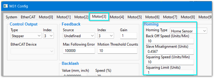
The slave motor Homing block is where all of the adjustments will be made. The units are your machine's calibration units - either inches or millimeters.
|
measure and work on gantry alignment by cutting squares
Multiply the amount the square is off by the width of the machine and enter that value into the offset field.
If your machine has an 8 foot wide table, and you cut a 1 foot square, and it was off by -0.005
8 * 0.005 = -0.040
table width * amount of offset needed = total offset
Add your offset. Move to a clear spot on the scrap and cut another square.
Measure the new square, multiply the error amount by 8 and add it to your existing offset
cut another square and you should be very close
Measure the new square, multiply the error amount by 8 and add it to your existing offset
Repeat the process until you have the quality you need
|
|
|
The slave misalignment value on the master motor is ignored, but it is best to set it to 0 for clarity. |
The slave misalignment value on the slave should be set to the value you need to square the gantry. The units is the same as the motors use - either inches or mm. Both positive and negatives are valid. |
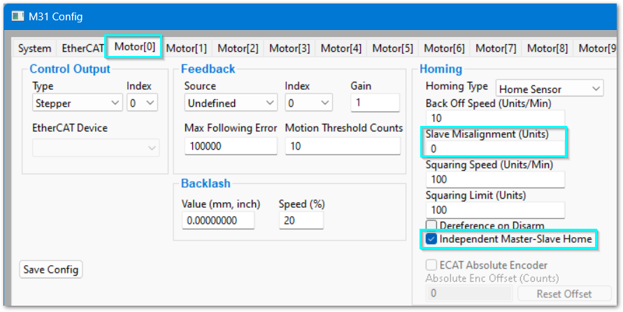
If you only have one home switch, on the master axis, then deselect theIndependent Master-Slave Homebox on both the master and slave motors. This tells the HiCON that both axes will use the same home switch.Map the home switch for the slave axis. In Configure | control | inputs find the input for the master axis' home, and map the slave axis to the same input.
|
|
| |
NOTES:
- There is an issue in some versions where the slave misalignment amount gets rounded once the Mach software has been closed. Be sure to test carefully after making your adjustment. Exit the mach software and restart and check the value to see if it has changed/rounded. If it does, there is an update for this. Please contact MachMotion for assistance.
- The
Back Off Speeduses rapid units (the max velocity and acceleration of the axis), and is the same units as the motor velocity.