
Mini Install Instructions
Tensile Mill Install
If the door will not lock ensure the solenoid is in the lock position
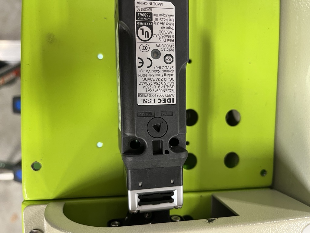
HMI ARM INSTALLATION
Use four M8 × 1.25 × 35mm hex-head screws

Mount Base of HMI Arm
Secure the HMI arm base to the cabinet using the four screws


Feed HMI Cables Through Cabinet and Arm


Insert and Tighten Arm Elbow
Install the horizontal arm (Cut to 13 1/2 inches), insert the internal cushion, then the elbow piece,
tighten screws,


Install vertical arm (Cut to 12 inches) and route Cables Into HMI Back Panel
Feed cables up into the rear panel opening of the HMI.


Step 7.6 — Before mounting HMI Rotate HMI to (Confirm Movement in the correct direction and not backwards)
Ensure the screen rotates freely in the correct direction. Install the keyboard and mouse tray along with the side handles.


Control Connections
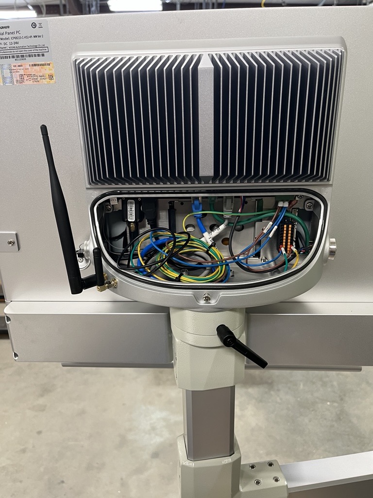
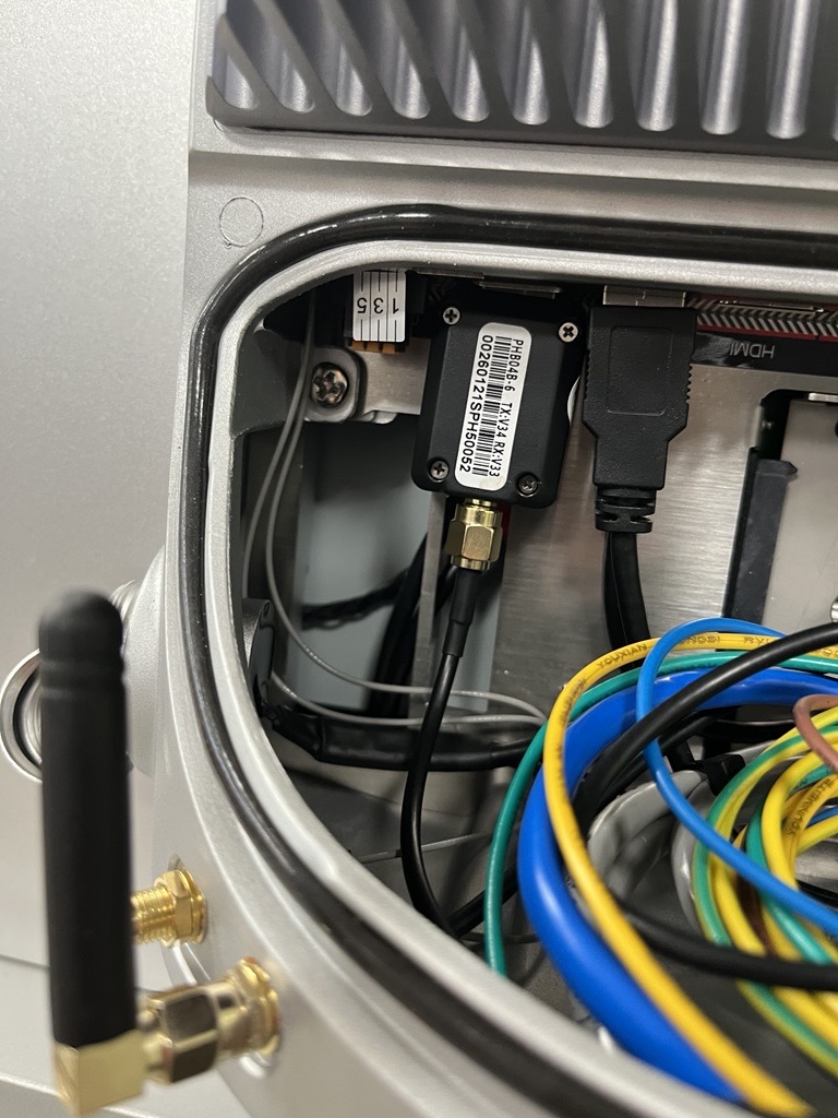
Replace the right antennae connector with the wireless pendant connector.
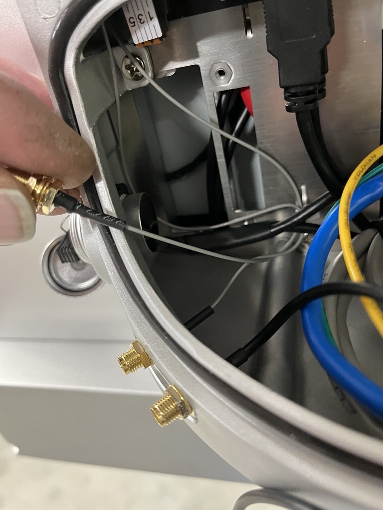
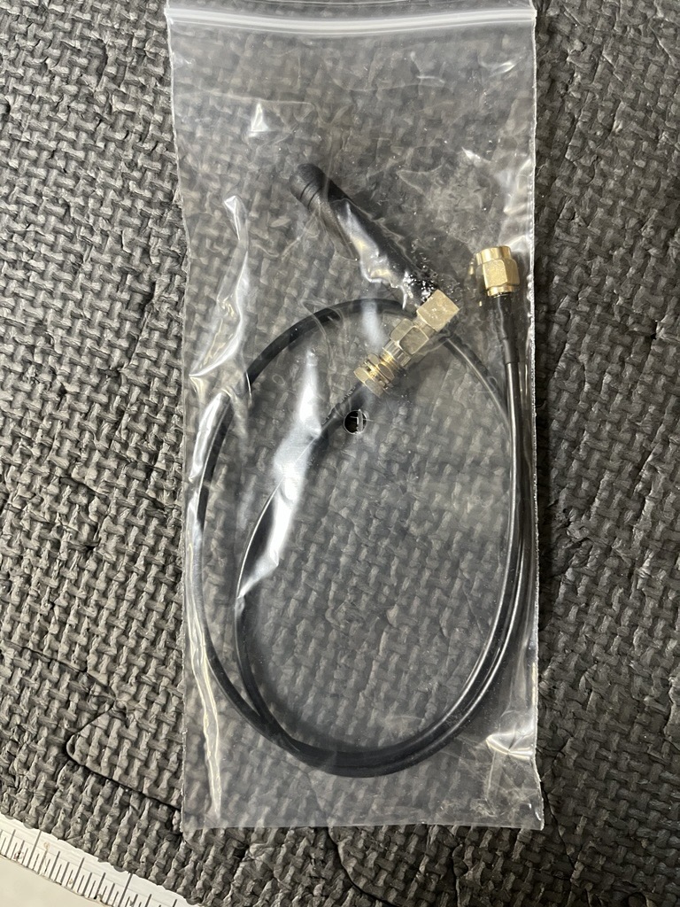
Plug the wireless pendant USB connector into the back USB and connect the cable between the two. Connect the antennae. Connect the Wifi antennae to the other screw connector.
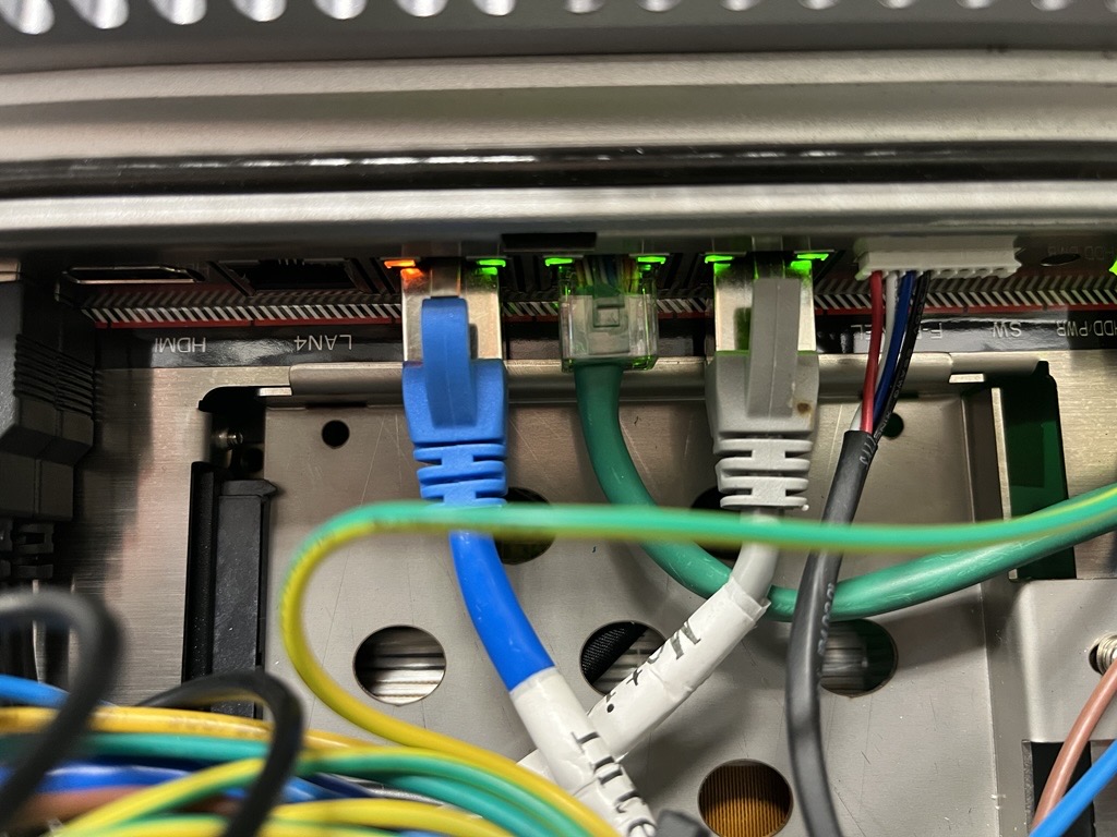
Connect the Internet cable to LAN3 and the Motion cable to LAN1.
Connect the ground wire to the ground location (upper right hand corner).
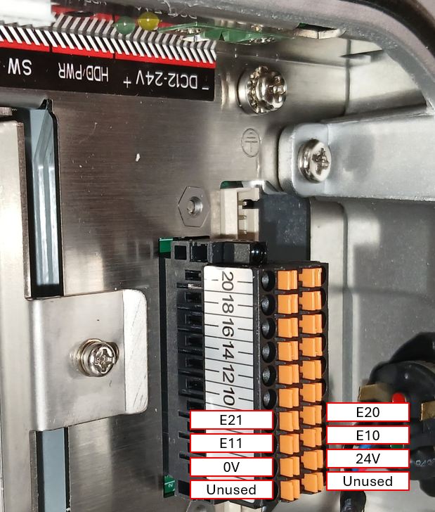
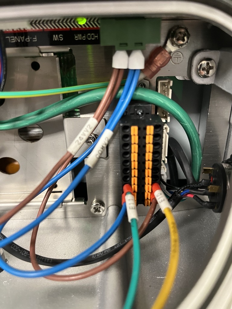
Double ferrule the incoming 24V and 0V with a small 6" jumper. Connect the double ferrule to the green plug and the jumpers to the block underneath accordingly. Connect the E10 and E11 wires to the same block accordingly. More than likely you will not have E20 and E21.
Mount and wire Tool Setter

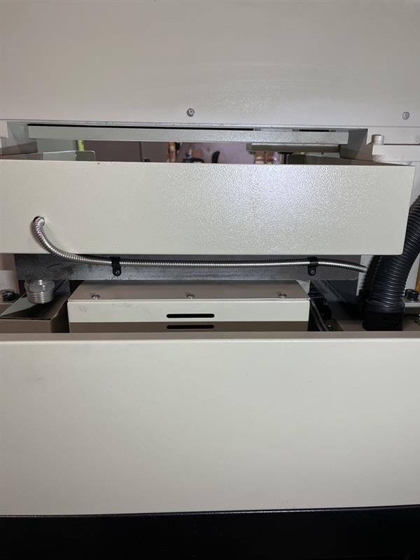
11.2- Run Tool Setter cable through the cable track

11.3- Run Tool Setter Cable out of the cable track and into the black loom, down into the cabinet

11.4- Wire the Tool Setter into the M31
Orange Wire- Tool Setter Touch- Label 6114- J1 Port 5
Blue Wire- Tool Setter Limit- Label 6116- J1 Port 6
Green Wire- 24VDC+ Common- Label 6115- J2 Port 2
Brown Wire- 24VDC+ Common- Label 6113- J2 Port 3
Red Wire- 24VDC+ Common- Label 6112- J2 Port 4
Grey Wire- 0VDC- Common- Label 0V- J11 Port 1

Mount the base plate
Clean any excess silicon from the mounting plate. (Razor blade, plastic scraper)
Place the t nuts on the edge and slide into position.
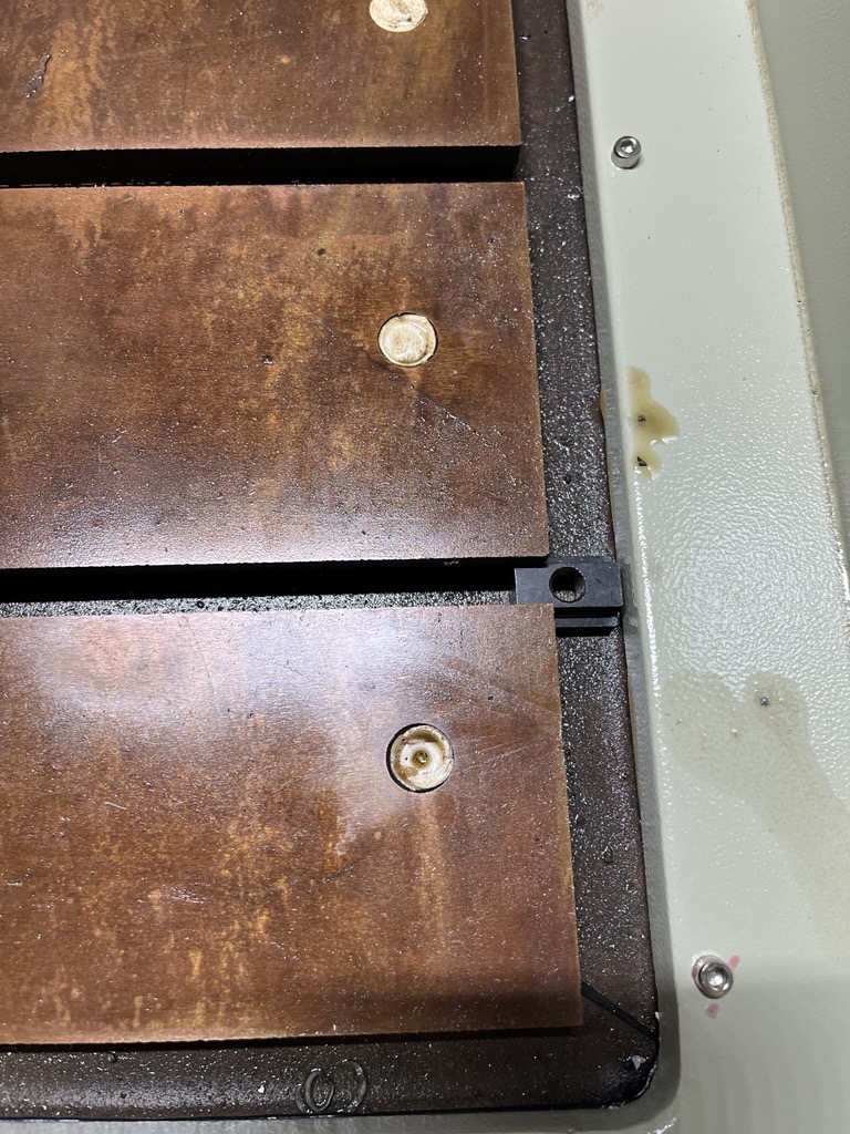
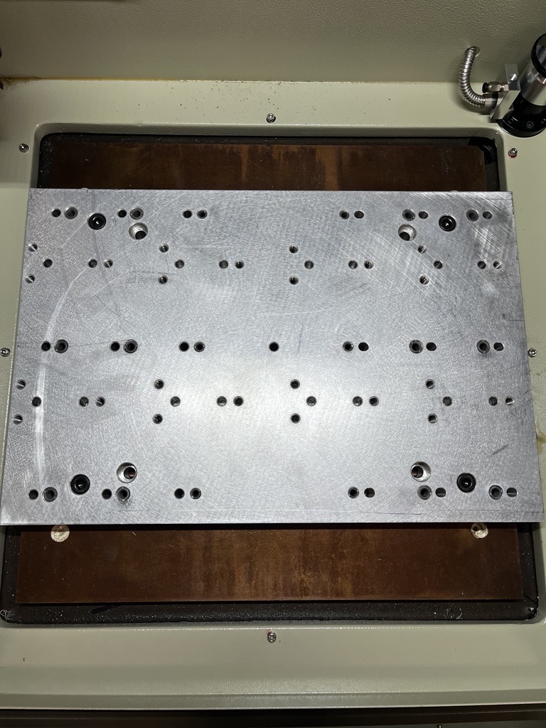
Evenly position the base plate and tighten down with the provided bolts
M31 CONTROLLER INSTALLATION & WIRING
Step 1.1 — Mount the M31 Controller
Install the M31 Motion Controller in the bottom-left section of the control panel.
Ensure it is firmly mounted and positioned so that the J1–J18 terminals face outward for wiring access.


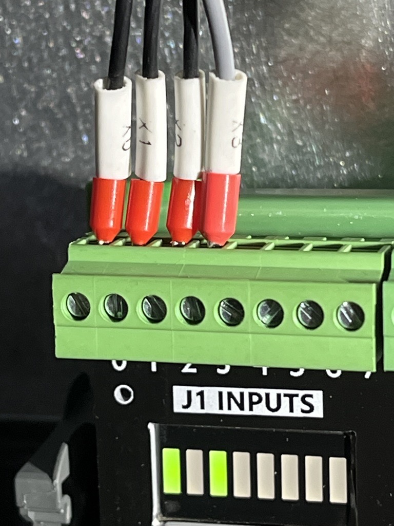
Step 1.2 — Install the X Limit Wire (X0) Into J1 Input 00
Step 1.3 — Install the Y Limit Wire (X1) Into J1 Input 01
Step 1.4 — Install the Z Limit Wire (X2) Into J1 Input 02
Step 1.5 — Install the Door Lock Input (X3) into J1 Input 03
SECTION 2 — EMERGENCY STOP WIRING
-
E10---ESTP
-
E12---+24V
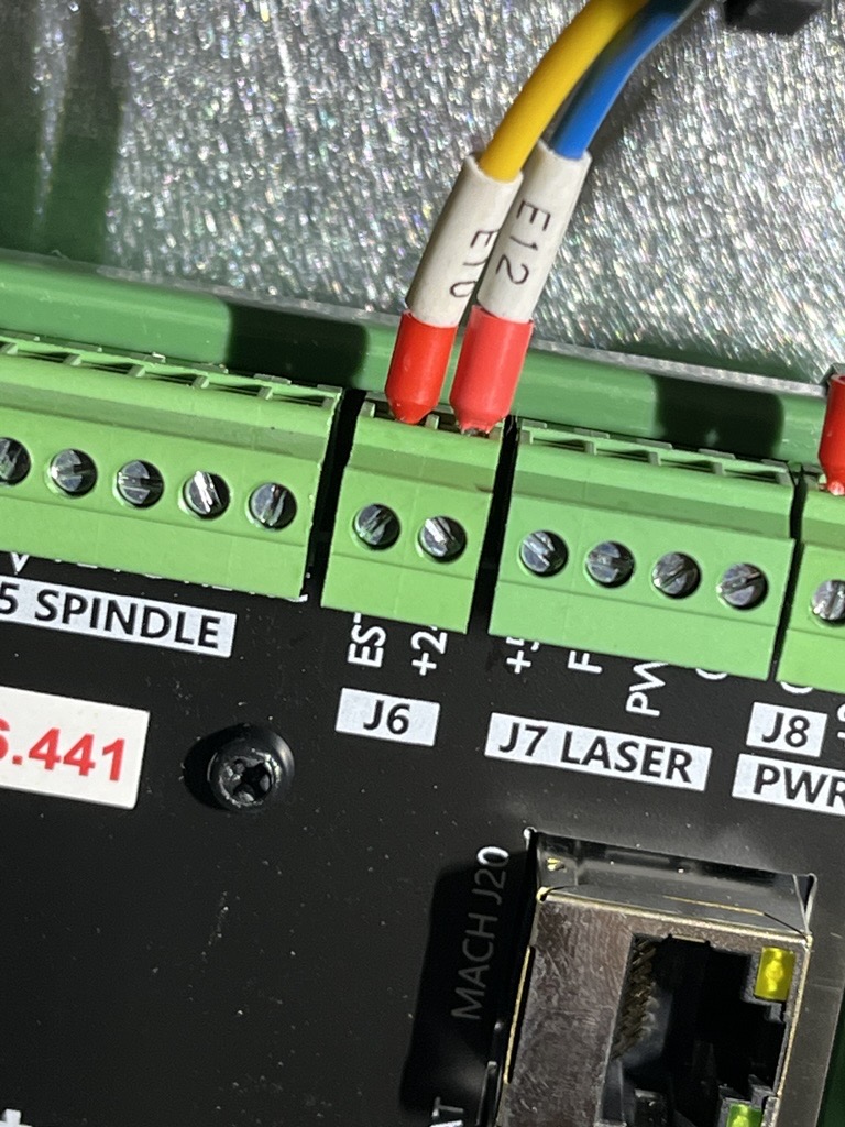
SECTION 3 — POWER WIRING
Connect the main 24V power to J8 Power:
-
24VV1---24V+
-
COMV1---0V
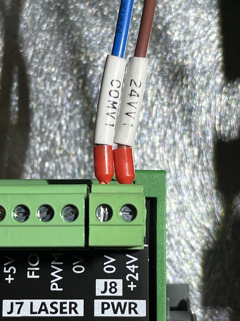
SECTION 4 — OUTPUTS AND RELAY WIRING
J10
Y1---J10-0
Y4---J10-1
Y2---J10-3
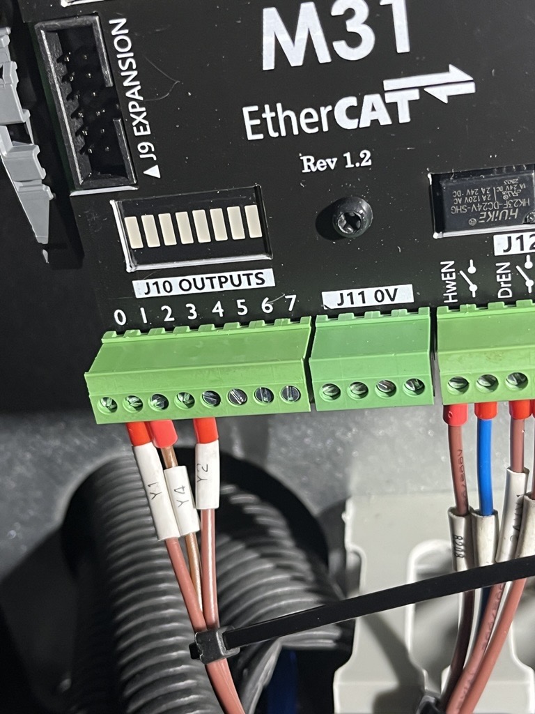
J12
- 8208----HwEN (J12-0)
- 8209----NO (J12-1)
- 24VV1--DrEN (J12-2)
- 8210----NO (J12-3)
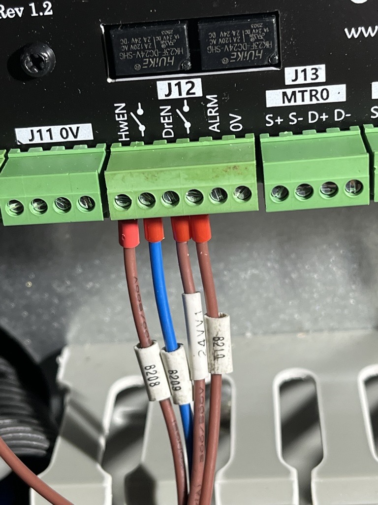
SECTION 6 — ETHERCAT CONNECTION
Connect the EtherCAT cable from the servo drives into the EtherCAT port on the M31.

Connect MACHJ20 Cable to HMI
Plug the top Ethernet port labeled MACHJ20 into the HMI LAN port.

BEFORE POWER UP
Remove the 24V Power Supply Terminal from the HMI and disconnect the jumpers. Turn the main disconnect and all other breakers on the unit off and connect power. Check in-voltage for correctness (240V). Turn main disconnect to on and check in coming power to all circuit breakers for correctness (240V). Turn on all circuit breakers. Check the HMI power connections for correctness (24V), then reattach them
SECTION 9 — SOFTWARE SETUP (HMI) Step 9.1 — Download Correct MachMotion Version
On the HMI:
-
Power on
- install machpro following the manual https://support.machmotion.com/link/1396
- Find latest M:\Production\Customer Backups\Tensilemill CNC Inc_Andrew Mahon\_Production Information
Step 9.3 — Rename Old Mach4 Folder
YOU MUST Rename existing Mach folder on the HMI to avoid any file conflicts. Failure to do this will cause lost work and errors.
-
Mach → Mach_old
Step 9.4 — Run TensileMill In House Mini Installer
Run the TensileMill In House Mini Installer, it should be located on the TensileMill USB for in house use. Make sure that the new folder created is named properly:
-
Mach (no spaces, no periods)
License Mach:
SECTION 10 — DRIVE SOFTWARE (VFD + SERVO) Step 10.1 — Install Required Software
The Drive software is not being installed on the control. The steps up to 10.6.2 will be done on/from a separate computer.
Install:
-
DCISoft 1.26 (for VFD)
- \\svr1.machmotion.local\MachMotion\Production\Products\Spindles\VFDs\Delta\MS300
- DELTA_IA-MDS_VFDSoft-V1-58_SW_20180725
- \\svr1.machmotion.local\MachMotion\Production\Products\Spindles\VFDs\Delta\MS300
- Leadshine software (for Servos) (witing the M Drive)
- \\svr1.machmotion.local\MachMotion\Production\Products\Drives-Servo\Leadshine\L7N
-
MotionStudio v2.3.2
Ensure computer/HMI has:
-
USB-B
-
USB-C (for Leadshine)
Step 10.3 — Locate Correct MS300 Software Version
Use: M:\Production\Customer Backups\Tensilemill CNC Inc_Andrew Mahon\_Production Information\VFD Parameters
DELTA_IA-MDS_VFDSoft_V1-58_SW_20180725
10.4.1 — Install the Software
-
Locate the installer file.
-
Right-click and select Run as Administrator.
-
Install using all default settings.
-
When completed, launch the program.
10.5 — Connect to MS300 VFD
10.5.1 — Prepare the VFD
-
Power ON the machine.
-
Ensure the VFD is connected to the control PC via your USB-A to USB-B cable
10.5.2 — Detect the VFD in Software
-
Open MDS VFDSoft.
-
Click Scan.
-
Select the COM port the USB adapter uses, this varies per machine, try in order.
-
Press Connect.
10.5.3 — Upload Correct Parameters
-
Load your saved MS300---M:\Production\Customer Backups\Tensilemill CNC Inc_Andrew Mahon\_Production Information\VFD Parameters
-
Press Write to Drive.
-
Cycle power to the VFD.
10.6.1 — Install Servo Utility (Example: Delta ASDA-Soft)
-
Open installer. (MotionStudio)
-
Install with default settings.
-
Connect USB-A to USB-C cable to servo drive.
- Open Device Manager and confirm Active COM (1-10) port. (Connection will not be established without correct COM port)
-
Open the utility software.
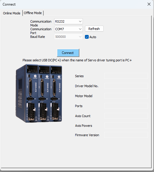
Step 10.6.2 — Set MotionStudio Language to English (Leadshine)
Open MotionStudio → Click language → select English → press Yes → restart.
Select COM Port we are using and RS232.
10.6.3 — Load Drive Parameters (Leadshine)
-
Identify each drive (X, Y, Z).
- Open the File tab on the MotionStudio overhead toolbar, then select Download Parameter Files.
-
Use parameters from here. M:\Production\Customer Backups\Tensilemill CNC Inc_Andrew Mahon\_Production Information\Drive Parameters
-
Write parameters to the drive. If a pop-up window asks if you would like to still write abnormal parameter changes, select the left button, which means "Confirm the issuance" in Chinese.
- Verify the parameters have updated by opening the Parameter List from the menu on the left in MotionStudio. All of the updated parameter values should be highlighted in red.
- Reopen the Connect tab on the top toolbar and click the Disconnect button.
-
Reboot the servo drive, either by power cycling manually or simply by removing the USB C cable if updating the parameters with the panel turned off.
- Move the USB C cable to the next drive and repeat this process.
THIS SECTION IS OUTDATED, PLEASE UPDATE
10.7.1 — Open VSI Device Manager
-
Launch VSI Device Manager.
-
Click Scan in the top-left.
10.7.2 — Select the Controller
After scanning, you should see a device with the following IP:
192.168.208.35
(This is the MachMotion M31 control board.)
-
Click to highlight 192.168.208.35.
-
Verify that the device information loads in the lower panel.
10.7.3 — Enter Loader Mode
In the lower panel of VSI Device Manager:
-
Click “Load Mode”
(sometimes labeled Boot Mode, Loader Mode, or Load Boot File Mode depending on software version)
The M31 will switch into loader mode, allowing firmware changes.
10.7.4 — Update the FPGA
-
Click Fast FPGA (button in lower panel).
-
Browse to the most up-to-date FPGA file provided by MachMotion.
(File extension is usually .rbf) -
Click Open / Write to begin flashing the FPGA.
-
Reboot the controller when prompted.
10.7.5 — Update the Firmware
After reboot:
-
Click Firmware Update (or Load Firmware File).
(Button is in the same lower panel as the FPGA option.) -
Browse to the 7.12(.bin). (in the mach/ motion controllers/ M31)
-
Click Write to flash firmware.
-
Wait for confirmation.
-
Reboot the controller again.
10.7.6 — Finalize
-
Close VSI Device Manager.
-
Power cycle the entire machine:
-
Turn OFF main power
-
Wait 10 seconds
-
Turn power ON again
-
This ensures the M31 loads the new firmware and FPGA.
Load EtherCat Configuration. Loading EtherCat Configuration
10.8 — Verify EtherCAT & Controller Status in Mach4
The following steps may not need to be done but verification that they are should be.
Password protection for CNC button and setup button. Set to Tensile123
After updating the FPGA and Firmware and power cycling the machine, you must confirm that Mach4 recognizes the controller and all EtherCAT devices correctly.
10.8.1 — Launch Mach
Open Mach4 normally from the HMI.
Wait for the main screen to finish loading.
A screen will appear with a Tensile button and a CNC button. Click the CNC button and enter the password:
10.8.2 — Check M31 Status
Open:
Diagnostics → M31 Status Panel
Verify: go to mach ( configuration/plugin/m31/ethercat/) after verifying upload refresh network ensure all devices are there then update - Okay - apply and restart mach software
-
Controller: Connected
-
Firmware Version: Updated
-
FPGA Version: Updated
-
EtherCAT: Running
-
Axis Drives: Enabled / Idle
-
No Faults or Lost Steps warnings
If anything shows red or Not Connected, power-cycle again.
10.8.3 — Check EtherCAT Devices
Open:
Diagnostics → EtherCAT
You should see:
-
M31 Controller
-
X-Axis Servo Drive
-
Y-Axis Servo Drive
-
Z-Axis Servo Drive
-
Any additional EtherCAT devices (IO blocks, tool setter blocks, etc.)
All devices should show:
-
Status: OK / Operational
-
Heartbeat: Active
If any drive is offline, check:
-
EtherCAT cable connections
-
Drive power
-
Termination (if required)
-
Drive alarms
10.8.4 — Verify Physical pokeys and Inputs/Outputs
Open Machmotion and go to Pokeys by going to (configuration/plugins/machmotion.com)
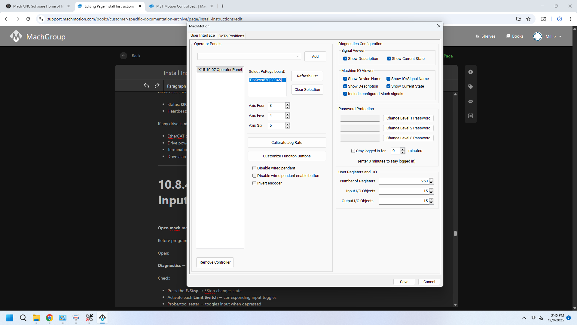
On this screen click Refresh List and then click Save.
(Edit: The screenshot and description of how to navigate to the window shown on the screenshot are confusing and accidentally imply the use of the internet to access the page.)
Proposed Updated Description:
In Mach, disable the control by pushing the Enable button in the bottom left corner of the screen, then go to the screen menu and click on Configure, then click on Plugins, then click on the Machmotion plugin. The window should load in, click on the X15-10-07 Operator Panel, then click on Refresh List, then click Save.
Before programming IO in Mach4, confirm that the hardware physically works.
Open:
Diagnostics → M31 I/O Monitor
Check:
-
Press the E-Stop → EStop changes state
-
Activate each Limit Switch → corresponding input toggles
-
Probe/tool setter → toggles input when depressed
-
Turn ON outputs manually (if toggling allowed) → coolant relay clicks / output LED activates
This proves the board and wiring are correctly connected before configuring Mach4.
10.9 — Program Inputs in Mach4 (Correct Method)
Now that inputs are verified, configure them in Mach4’s control system.
10.9.1 — Open the Control Configuration
Click the Input Signals tab.
10.9.2 — Assign Each Machine Input
For each input:
-
Check Enabled
-
Device should be set to M31
-
Set the correct Input Number (0–7 depending on J1 terminal)
-
Set Active Low if your switch is wired Normally Closed (NC)
Recommended Mapping (Based on Your Wiring):
| Function | Mach4 Signal Name | M31 Input # | Physical Terminal |
|---|---|---|---|
| X Limit | X-- | 0 | J1-00 |
| Y Limit | Y-- | 1 | J1-01 |
| Z Limit | Z-- | 2 | J1-02 |
| Probe | Probe Input | As wired | J1-xx |
| E-Stop | EStop | ESTP input | J6 |
10.9.3 — Save Inputs
Click OK, then restart Mach4 when prompted.
10.10 — Program Outputs in Mach4
Now configure coolant, spindle enable, and any auxiliary outputs.
10.10.1 — Open Output Signals
10.10.2 — Assign Outputs
For each output:
-
Enable the output
-
Set Device to M31
-
Assign Output # (0–7 depending on J10 terminals)
Your Likely Output Mapping:
| Function | Mach4 Output | M31 Output # | Terminal |
|---|---|---|---|
| Coolant Pump | Flood | 0 | J10-00 |
| Mist (optional) | Mist | 1 | J10-01 |
| Spindle Enable | SpindleOn | 2 | J5 or J10-02 |
| PWM Spindle/Laser | PWM | J7 PWM pin | J7 |
If a relay behaves backward, toggle Active Low.
Toggle the Coolant Pumps on and listen for the motor running, the motor needs to be plugged into the outlet on the electrical panel. The flood coolant tank doesn't need any coolant in it to test the pump, but don't run the pump very long without coolant.
10.10.3 — Save Outputs
Click OK
Restart Mach4.
10.11 — Configure Homing & Soft Limits
Homing MUST be set up before calibrating the machine.
10.11.1 — Open Homing Settings
Mach4 → Configure → Control → Homing/Soft Limits
10.11.2 — Assign Homing Order
Recommended order for a tensile mill:
-
Z Axis — Home Order 1
-
X Axis — Home Order 2
-
Y Axis — Home Order 3
10.11.3 — Set Homing Directions
Based on typical tensile mill design:
-
Z homes Positive (UP)
-
X homes Negative
-
Y homes Negative
Reverse direction in Motor Config if needed.
10.11.4 — Test Homing
Click Ref All Home
Verify:
-
Z raises to switch
-
X moves to its limit
-
Y moves to its limit
-
No axis crashes or moves opposite
If incorrect direction:
Mach4 → Configure → Control → Motors → check Invert Motion
To set the soft limit for Z Axis, there should be at least 2 inches of clearance between the flat face of the bottom of the spindle and a tensile clamp properly seated into the aluminum slab with its locating pins. There is a measuring block that can be used to get the proper minimum Z Limit position per machine. Jog the spindle down towards the table with the block to the side so it will not crash, then check the gap when not jogging. Get it close enough to not have a lot of wiggle room. Disable Mach and open the Configure tab on the system menu, then click on the Control option. In the Control window, open the Homing/Soft Limit tab and make the minimum Z Limit match the Z value on the machine display, press your Enter key, then click Apply and Ok. If you cannot see the buttons on the bottom of the popup window to Apply the changes, manually drag the corner of the window larger. The minimum soft limit for the Z Axis should be fairly consistent across the machines if the spindles were moved up to a consistent height.
10.12 — Axis Calibration (from Your PDF)
Based on “mach4-axis-motor-calibration.pdf”
Mach4 supports Manual and Automatic axis calibration.
10.12.1 — Open Calibration Tool
Mach4 → Configure → Plugins → Machine Calibration
Choose Manual Calibration or Automatic Calibration.
Manual Calibration Procedure (Recommended for Precision)
10.12.2 — Manual Calibration Steps
-
Select the axis (X/Y/Z).
-
Enter a commanded distance (e.g., 2.0000 inches).
-
Click Enable.
-
Click Move.
-
Measure actual travel using:
-
Dial indicator
-
Caliper
-
Gauge block
-
-
Enter the actual distance traveled.
-
Click Submit — Mach4 calculates new Steps Per Unit.
-
Click Accept.
Repeat for each axis.
Automatic Calibration Procedure
10.12.3 — Automatic Method
Enter:
-
Motor model
-
Gear ratio
-
Ball screw pitch
-
Microstep setting
Mach4 calculates theoretical values and loads them.
Fine-tune afterward with manual calibration.
(Edit: More details needed on checking calibration. What method should be used? What tolerance standard are we trying to reach?)
Find the switch for the aimable work light and turn it on to verify that the light works.
10.13 — Final Machine Validation Checklist
Before running production or test cycles, verify:
10.13.1 Mechanical
✔ All axes home correctly
✔ No binding or sticking
✔ Motors run smoothly
10.13.2 Electrical
✔ IO states correct
✔ Outputs activate correct devices
✔ All limits function
✔ E-stop functions every time
✔ No servo drive alarms
✔ VFD responds to Mach4 commands
10.13.3 Software
✔ EtherCAT online
✔ M31 connected with firmware/FPGA updated
✔ Correct Mach4 profile loaded
✔ Calibration accuracy within tolerance
✔ Soft limits verified
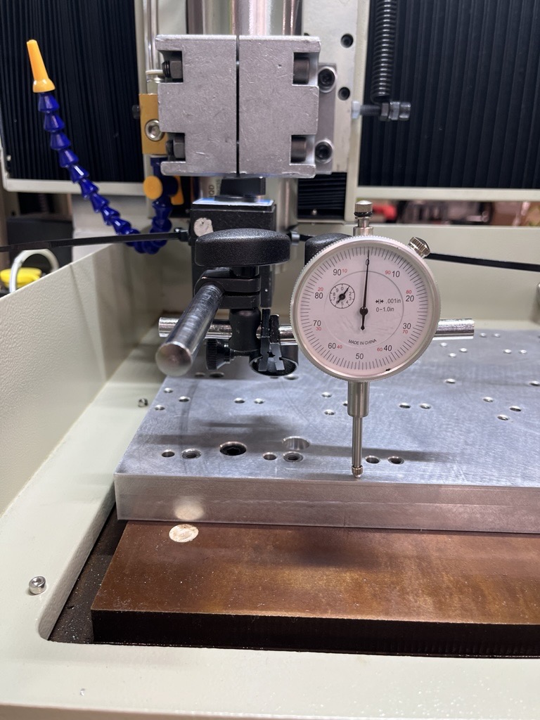
After the machine has been fully set up the base plate needs to be checked for square and level in relation to the spindle.
Place the dial indicator on the spindle and secure the top with zip-ties.
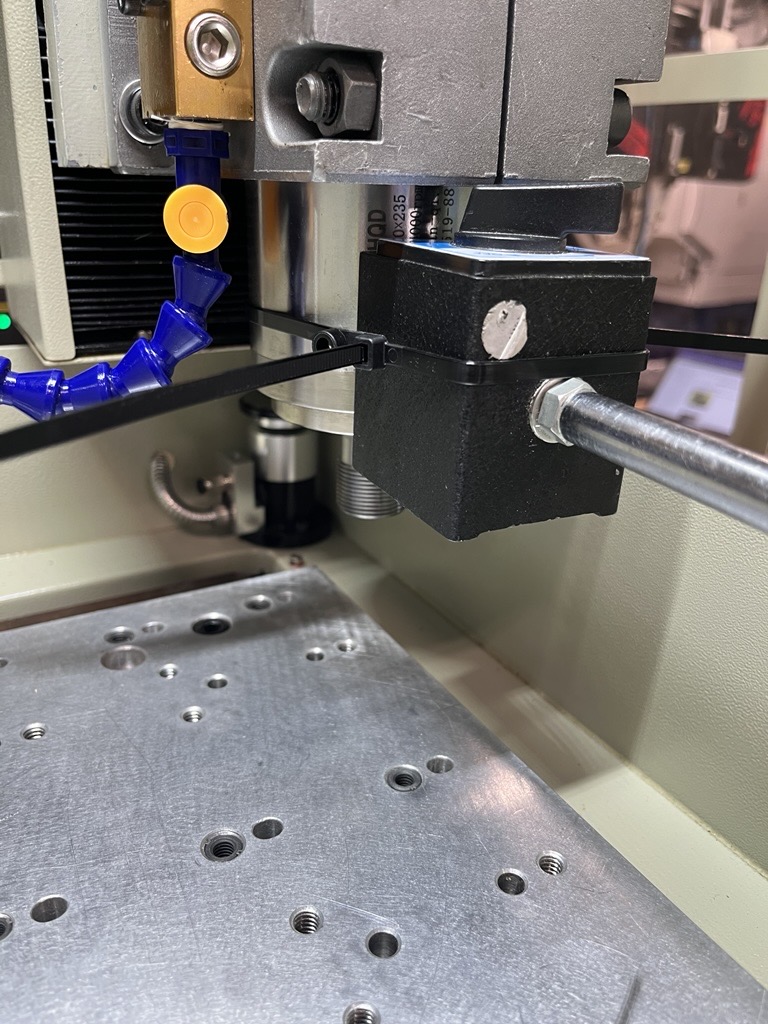
Position the dial indicator so that the probe will run across the front of the base plate along the x-axis.
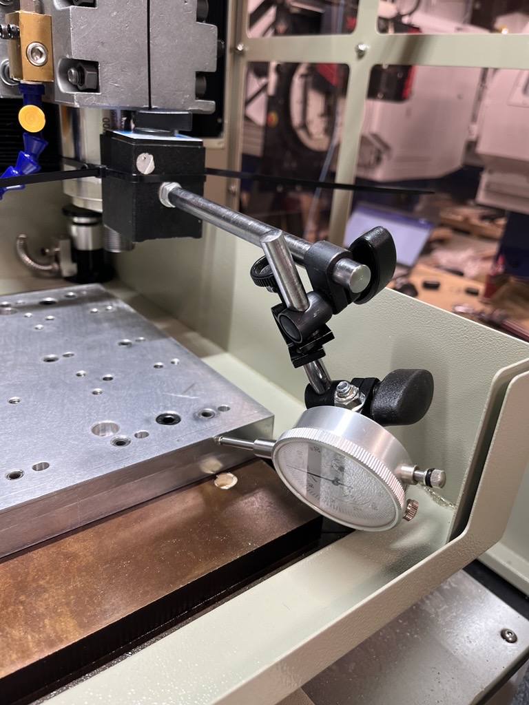
While commanding movement there should be less than 1 thousandth variation. adjust the base plate as necessary.
Next position the dial indicator so that it will run across the top of the plate.
While commanding motion there should be less than 1 thousandth variation. Adjust the base plate as necessary.
SPINDLE TESTING SECTION
DO NOT RUN THE SPINDLE WITHOUT THE COOLANT SETUP AND THE COLLET ASSEMBLY PROPERLY INSTALLED.
Setting Offsets
Find the collet nut, collet, and a tool to put in the collet. There should be a 1/2 inch collet included in the toolbox. The shank of the tool should be even with the back of the collet before you thread the collet nut on and tighten it with the included wrenches.
To set your fixture offsets, go to the Fixtures page, then locate the center hole on the aluminum plate, line up your bit with the hole in the aluminum plate and slowly lower Z Axis height into the hole while hand spinning the bit to make sure it is not scraping the walls of the hole. Once it is centered in the hole and about 1/4" below the plate surface in Z Axis, zero your X and Y Axis offsets. Carefully raise your Z Axis, move to an area of the plate without holes in it, set a piece of paper towel down on it, then slowly lower your Z Axis onto it while hand spinning it until the bit catches on the paper towel. Zero your Z Axis offset now.
Move your Z Axis all the way up, then carefully jog the spindle over to the tool setter. Your goal is to center the tool above the tool setter in a safe starting position. Once you have it lined up, open your Service page, go to the Maintenance tab, then open the Interface Config button. Once the Interface Config window opens, click on the Goto Positions tab and select Tool Setter Start. Click on the first line of Gcode, which should be for Z Axis, then click the Select Current Position button next to the Z Axis position line, then click Update. Click on the second line of Gcode and repeat the process for X and Y Axises.
Use a black wash bucket per machine for the spindle coolant, one gallon of distilled water should be sufficient for each machine, 5 gallons of distilled water total.
Take the spindle coolant pump off of the mount on the lid to ensure it will fully submerge in the bucket. blue tubing is installed into the pump and through the coolant tank lid.
Remove the collet nut, collet, and tool at this point. Wrap the threads of the spindle nose with electrical tape to make a flat, non-reflective surface, then place a piece of reflective tape on the electrical tape. There should be a small amount of reflective tape in the tachometer case. Open the MDI window and type in M3 S1500, which will command Spindle Forward at 1500 RPM. Open the GMS window and disable the Door Open and Door Open Alarm. This should allow you to run the spindle with the door open, but the speed is hard coded to be limited to 1500 RPM while the door is open. Press Cycle Start, then use the tachometer to measure actual speed. The actual speed should be within 50 RPM of the commanded speed.
24 HOUR TESTING AREA
Go to the Tensile Screen, you should start on the Define Specimen screen, find the RPM setting and change it to 3000 RPM, then toggle the Coolant button until it turns green and then gray again. Next, click on the Run Specimen button, wait for the toolpath to load in, then click on the Setup tab, then click on the Setup button. Enter the password into the popup window. Push the Edit Gcode button, then look through the code until you find M30, change M30 to M99, Go to the Fixtures screen, then locate your Z Axis Work Shift Offset. Edit the offset so that it will be 2 inches. The program should be fully ready to run on repeat now, close the doors and push Cycle Start.