
Micro Install Instructions
1. Unpack the Micro Mill
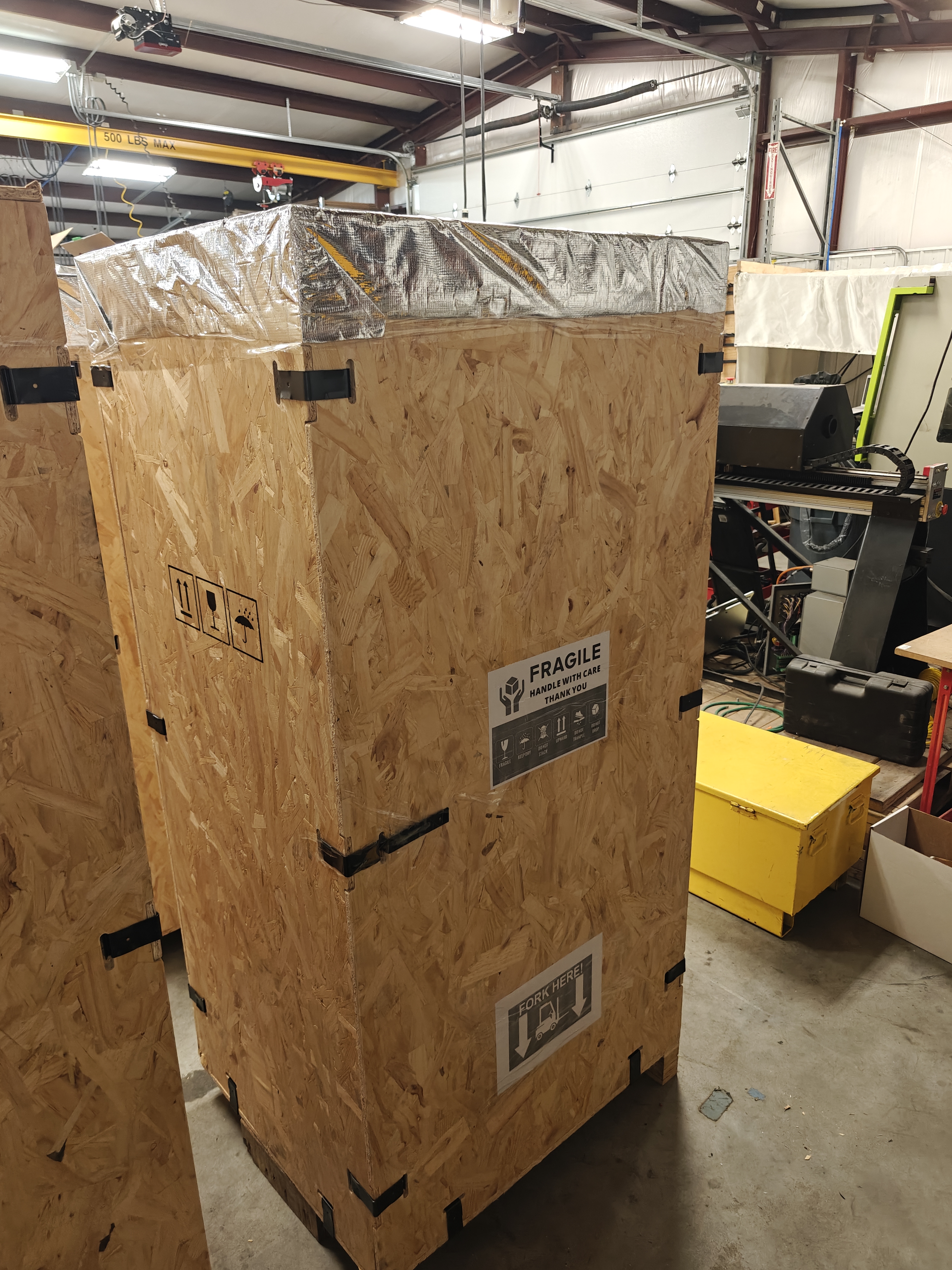
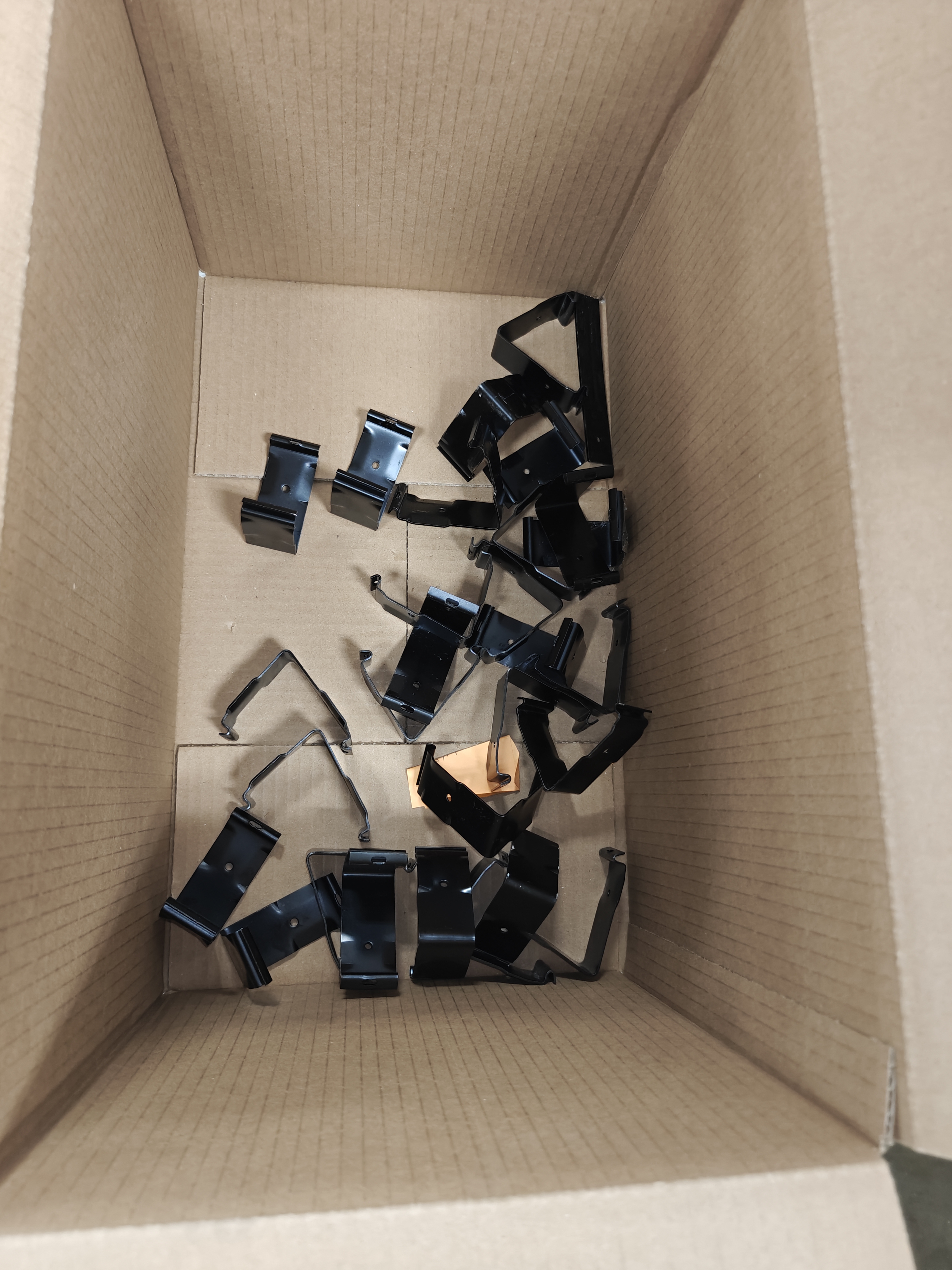
Remove the foil top cover over the crate and throw it away. Remove the clips in order and carefully remove the crate panels. Put all of the clips in a box so they don't get lost. The crate panels should go on a pallet so they can easily be moved around. Take the top one off first. Take off the layers of shrink wrap, keep the shiny bag and the plastic bag, cut the disposable strapping.
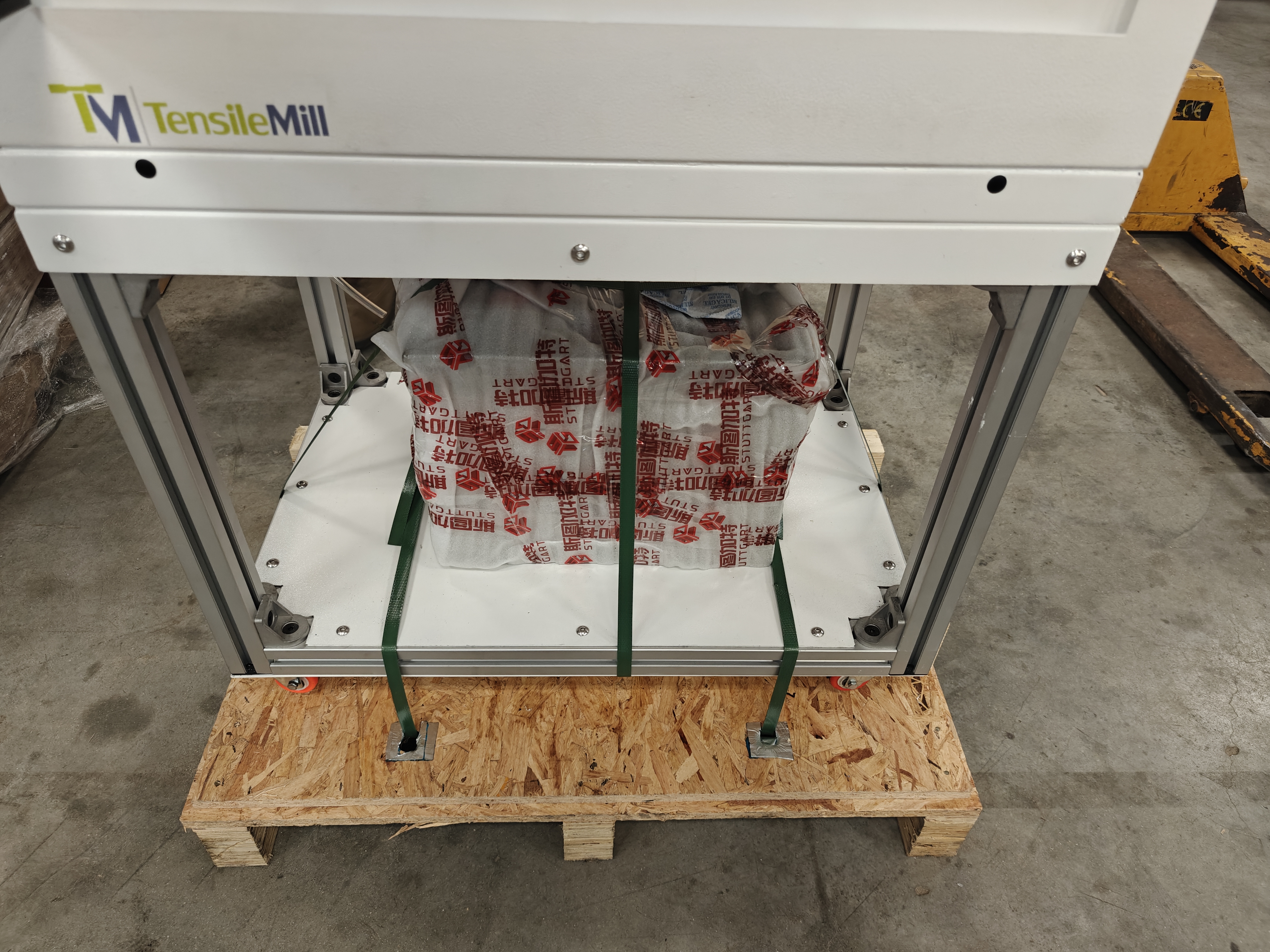
Keep straps from the pallet over the base of the machine on, only cut the straps that go over the coolant tank. We will need to unpack the coolant tank enough to run the motor to verify that it works.
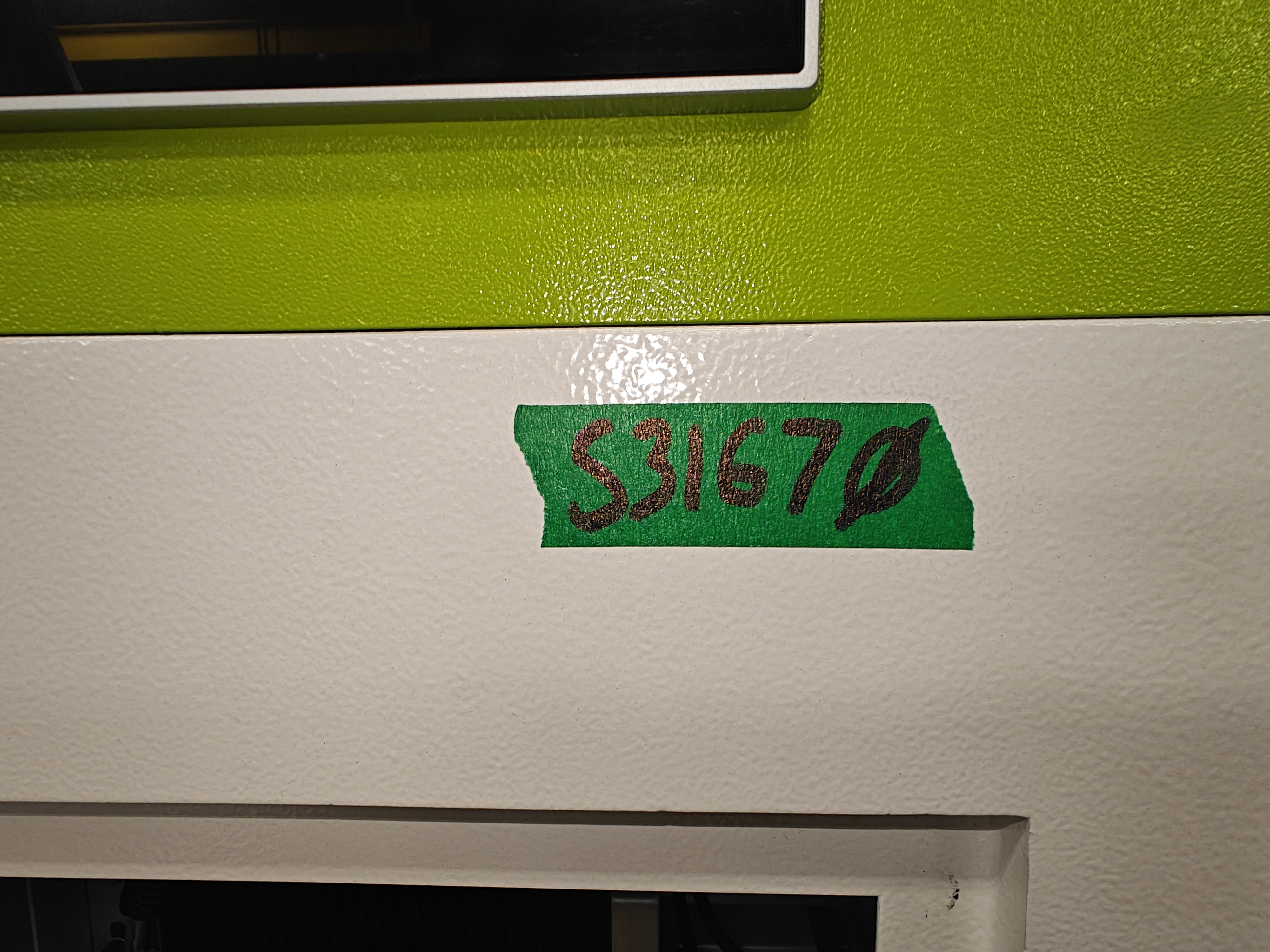
Look at Odoo and find the Sales Order numbers for the machines you will be working on. Use a piece of tape on the front of each mill and write the Sales Order number for that mill. Just assign each machine one of the Sales Order number, this will help you keep track of issues on each machine.
2. Mount and Wire in the M31 Board
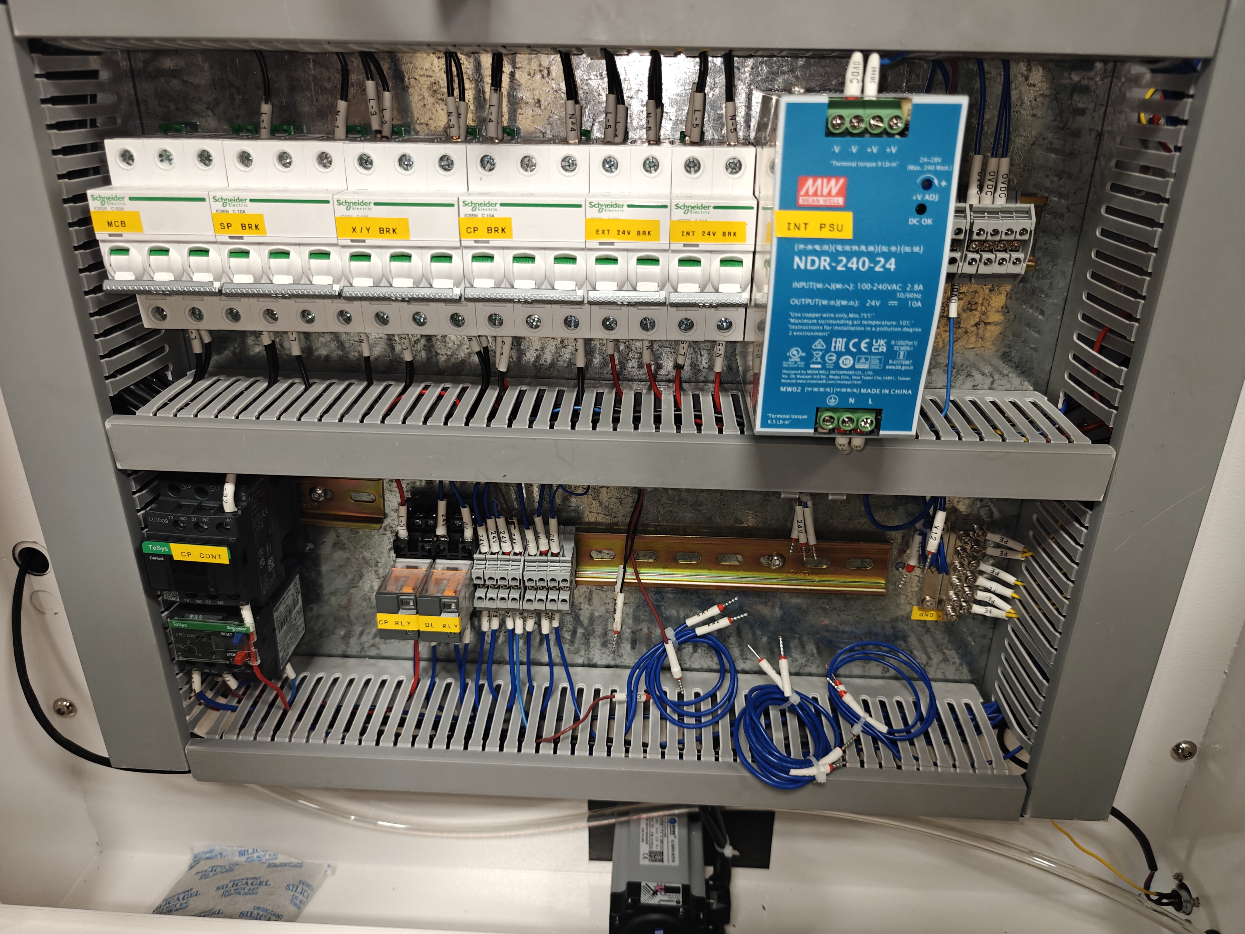
Attach the M31 board here.
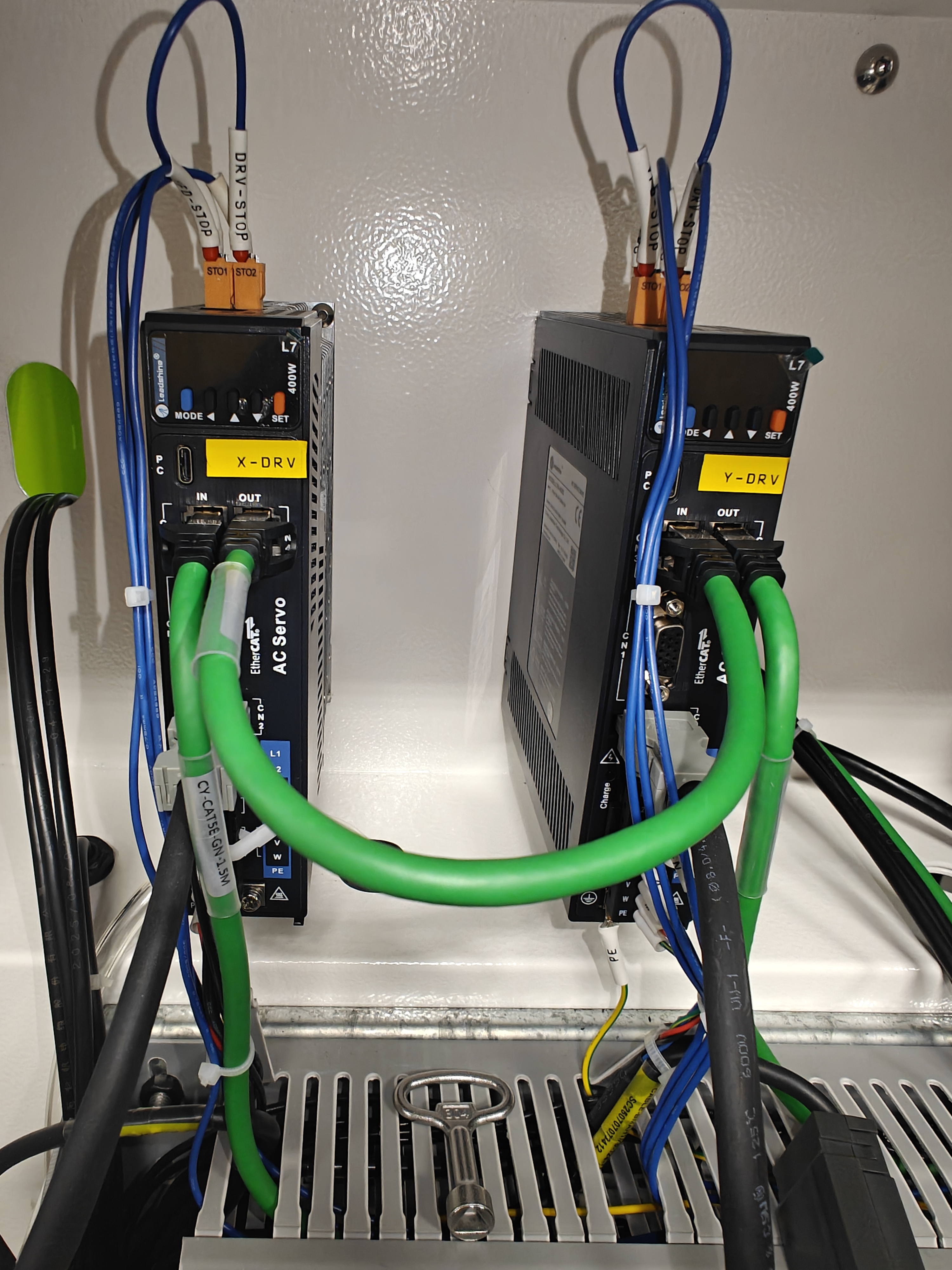
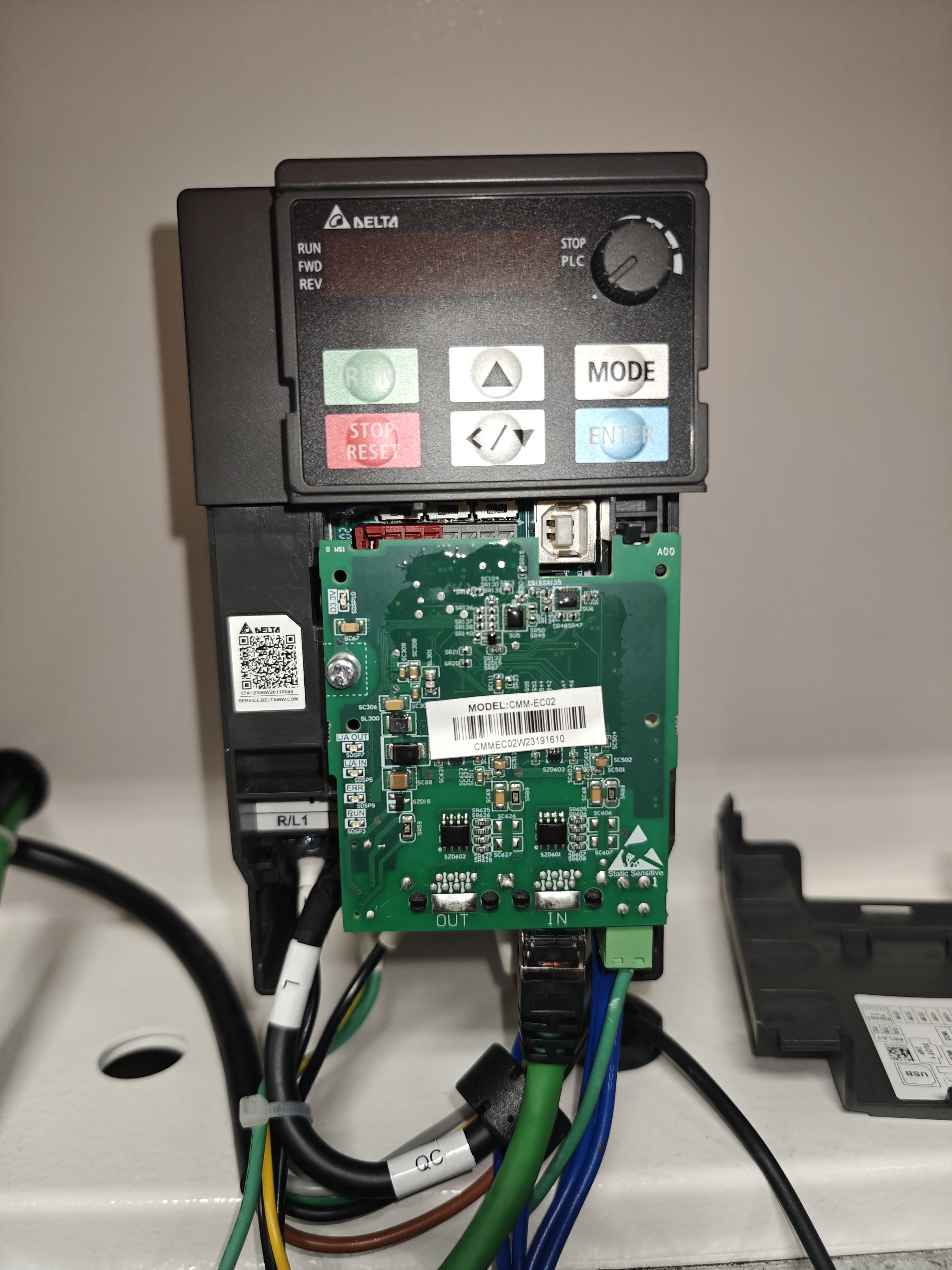
The ethernet cables are typically plugged in wrong. Verify that the loop starts at the M31 and ends at the VFD. The first cable in the chain on the right should start at the M31 board and go to the In port on the first drive, the second should go from the Out port to the In port on the second drive, the third should go from Out port to the VFD In Port.
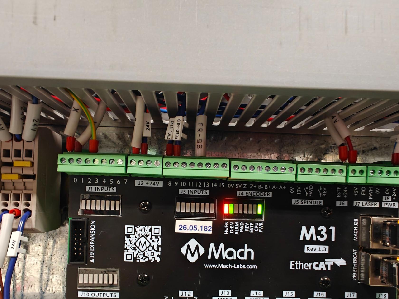
J1 Inputs: X Limit into J1.0?, Y Limit into J1.1?, Ground into J1.3?
J2 +24V: Unknown into Slot 1, Wire labeled 24V into Slot 2.
J3 Inputs: CYCL-STRT into J3.8, FEED-HLD into J3.9, FR-85? into J3.12,
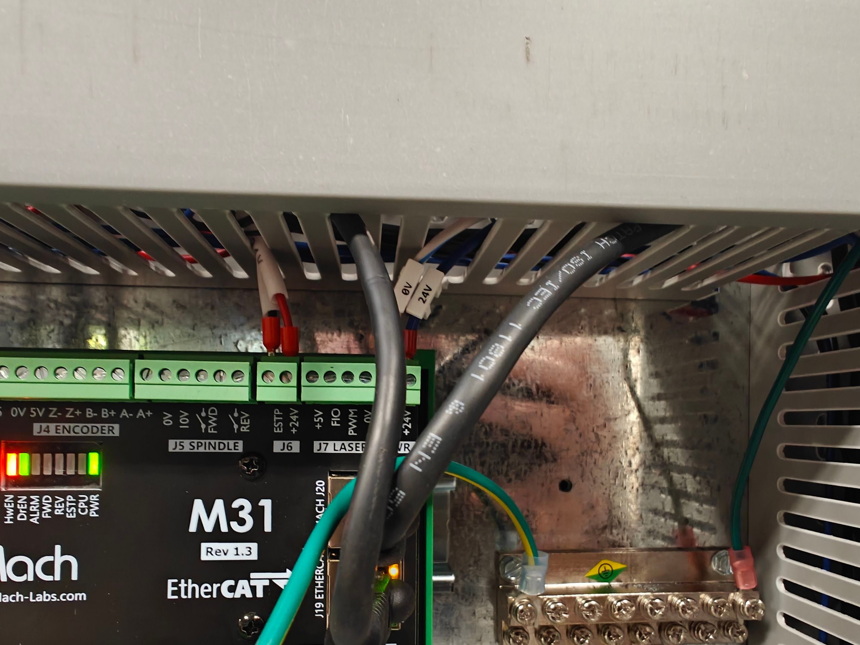
J6: Unknown into Slot 1, Unknown into Slot 2
J8 PWR: 0V into Slot 1, 24V into Slot 2
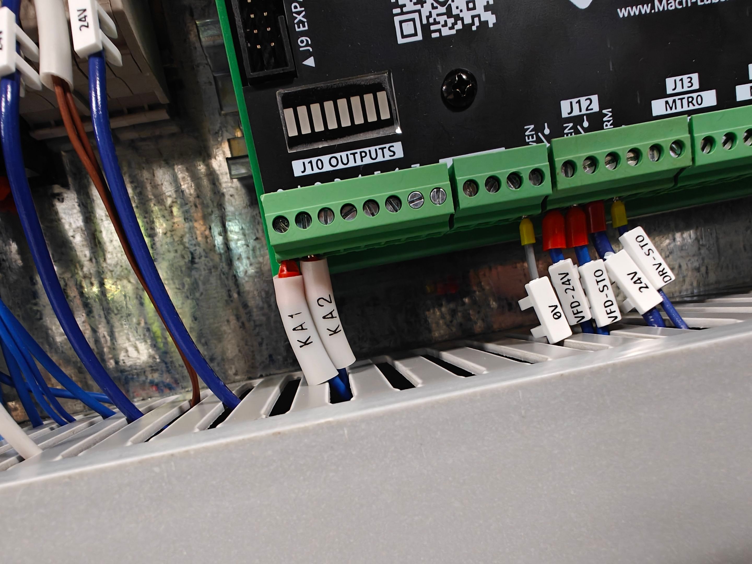
J10 Outputs: KA1 into J10.0, KA2 into J10.1
J11?: 0V into Slot 4.
J12: VFD-24V into Slot 1, VFD-STO into Slot 2, 24V into Slot 3, DRV-STO into Slot 4
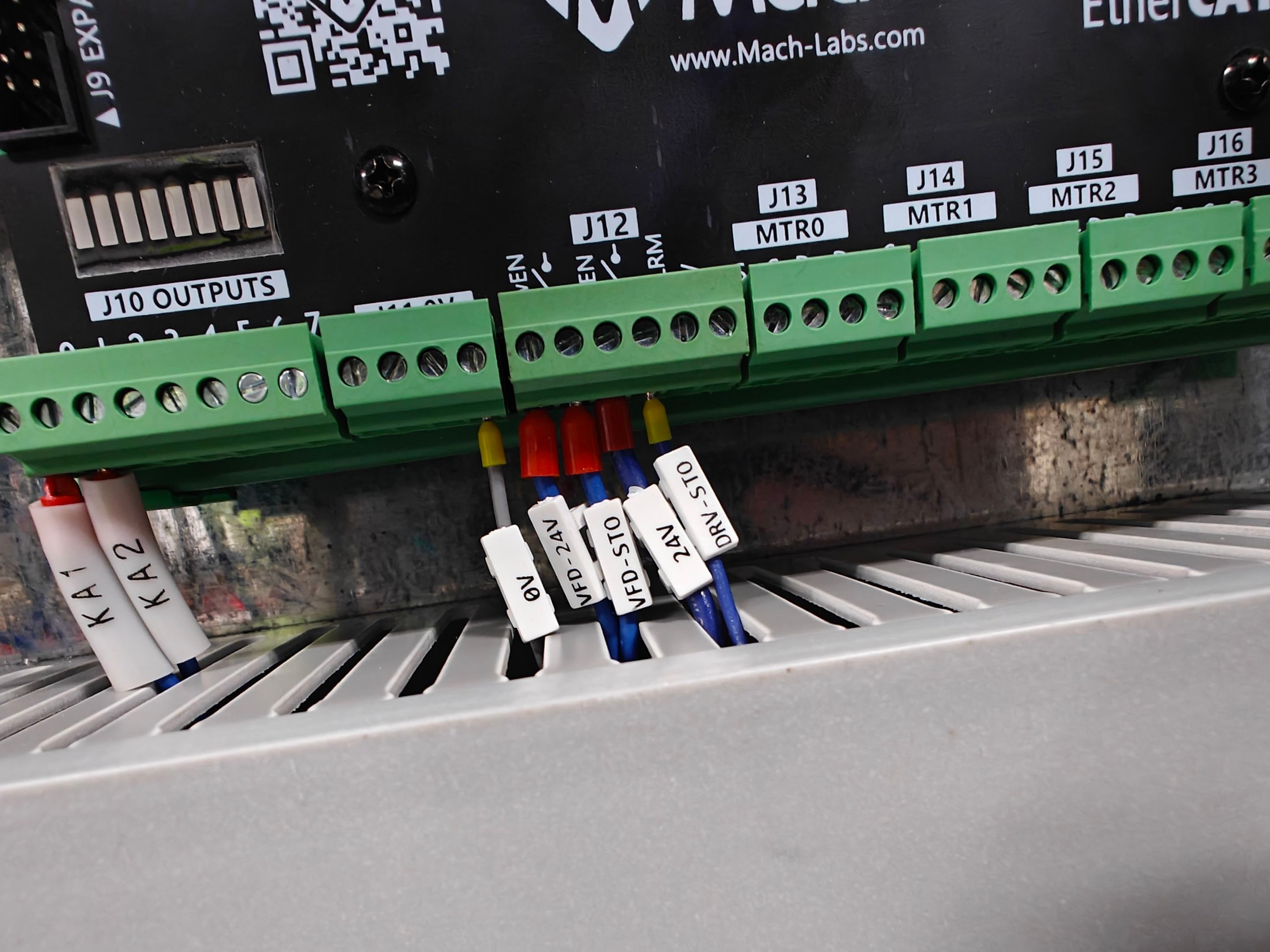
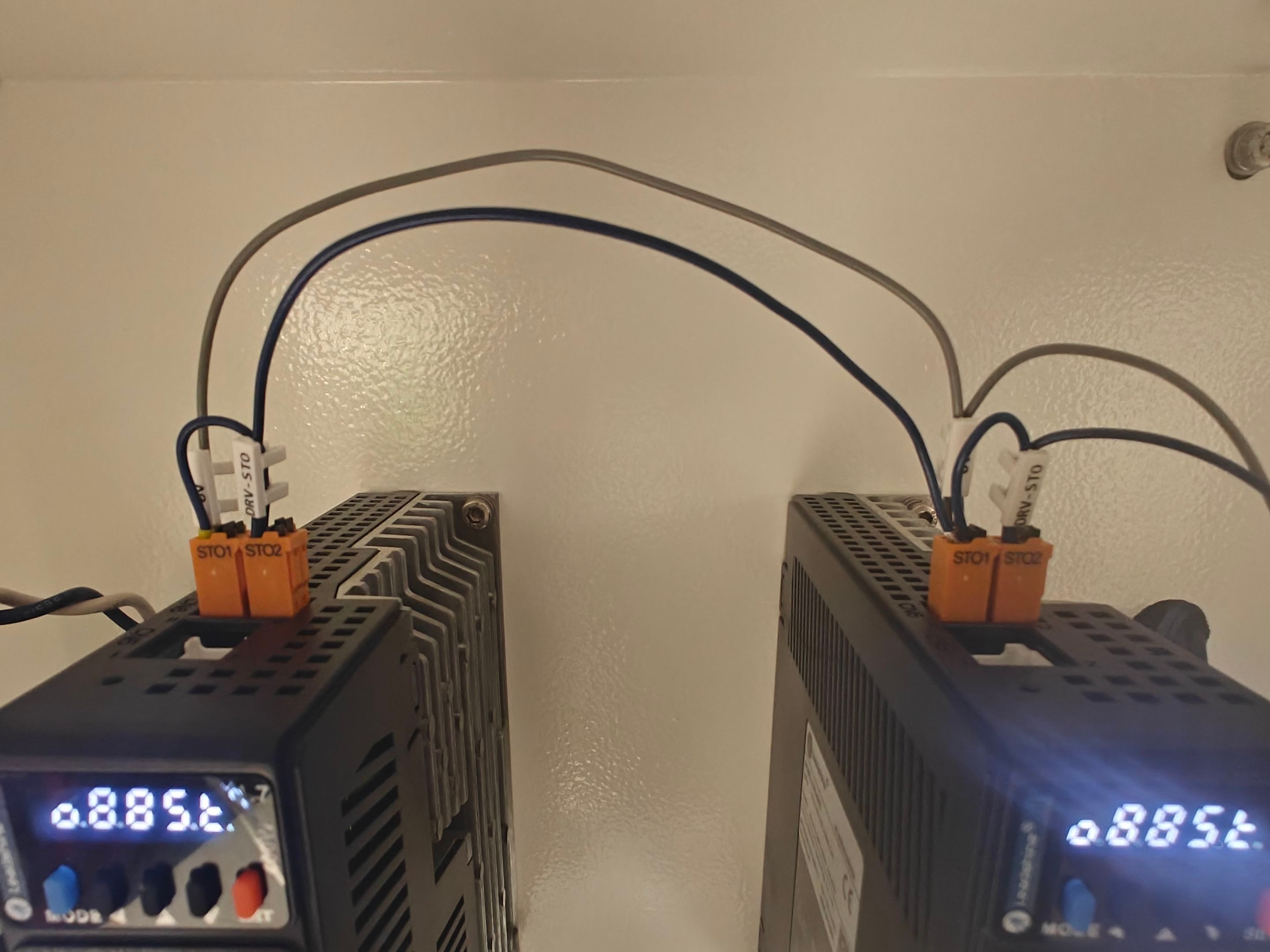
Check on the STO wiring for the X and Y Axis drives. The Gray wire should jumper to both of the COM terminals on the blocks, and the Blue wire should jumper across the STO1 and STO2 on both drives.
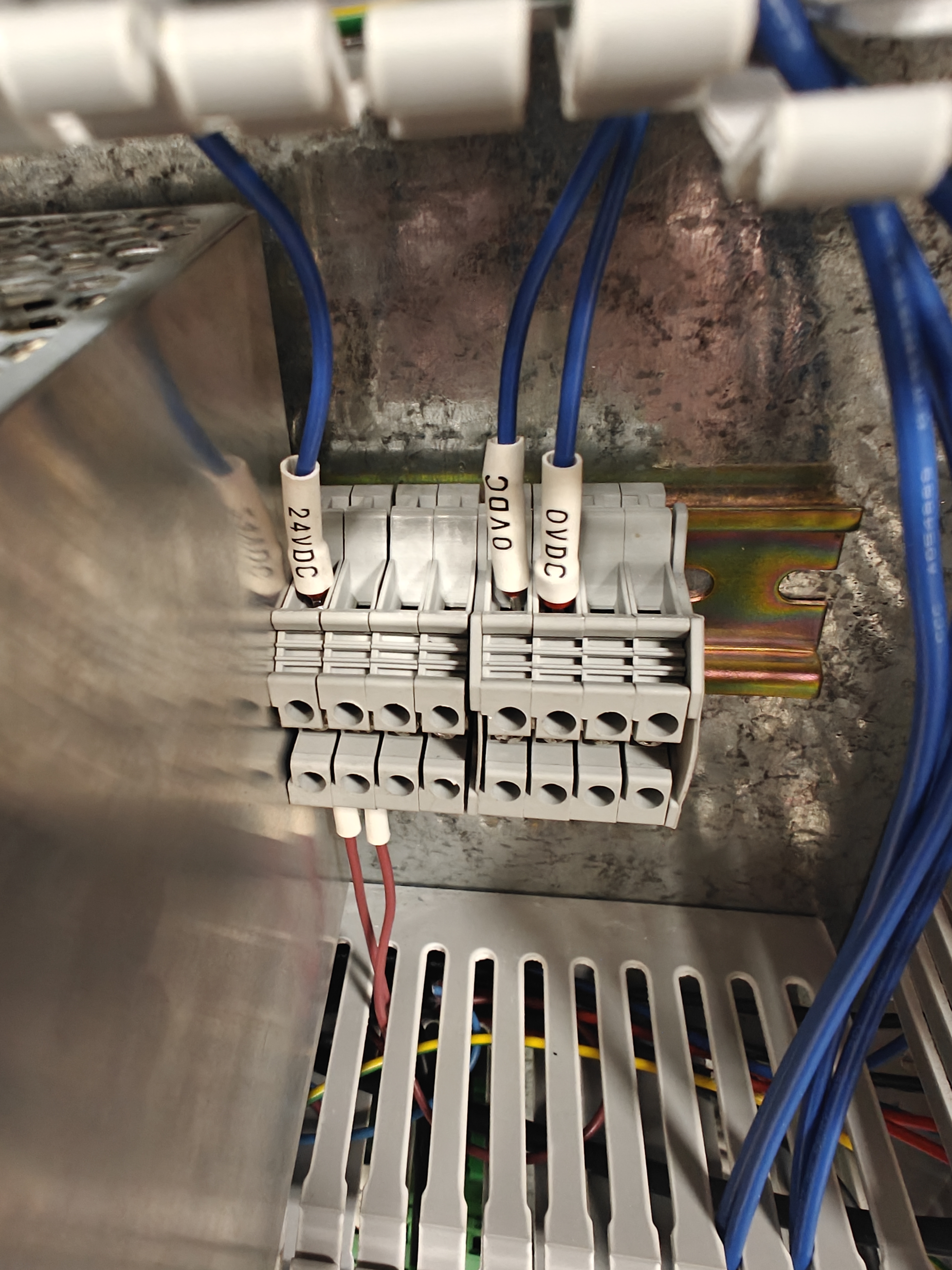
Wire the jumpered terminal blocks next to the Int Power Supply to the other power supply, 24V to the V+, 0V to the V-.
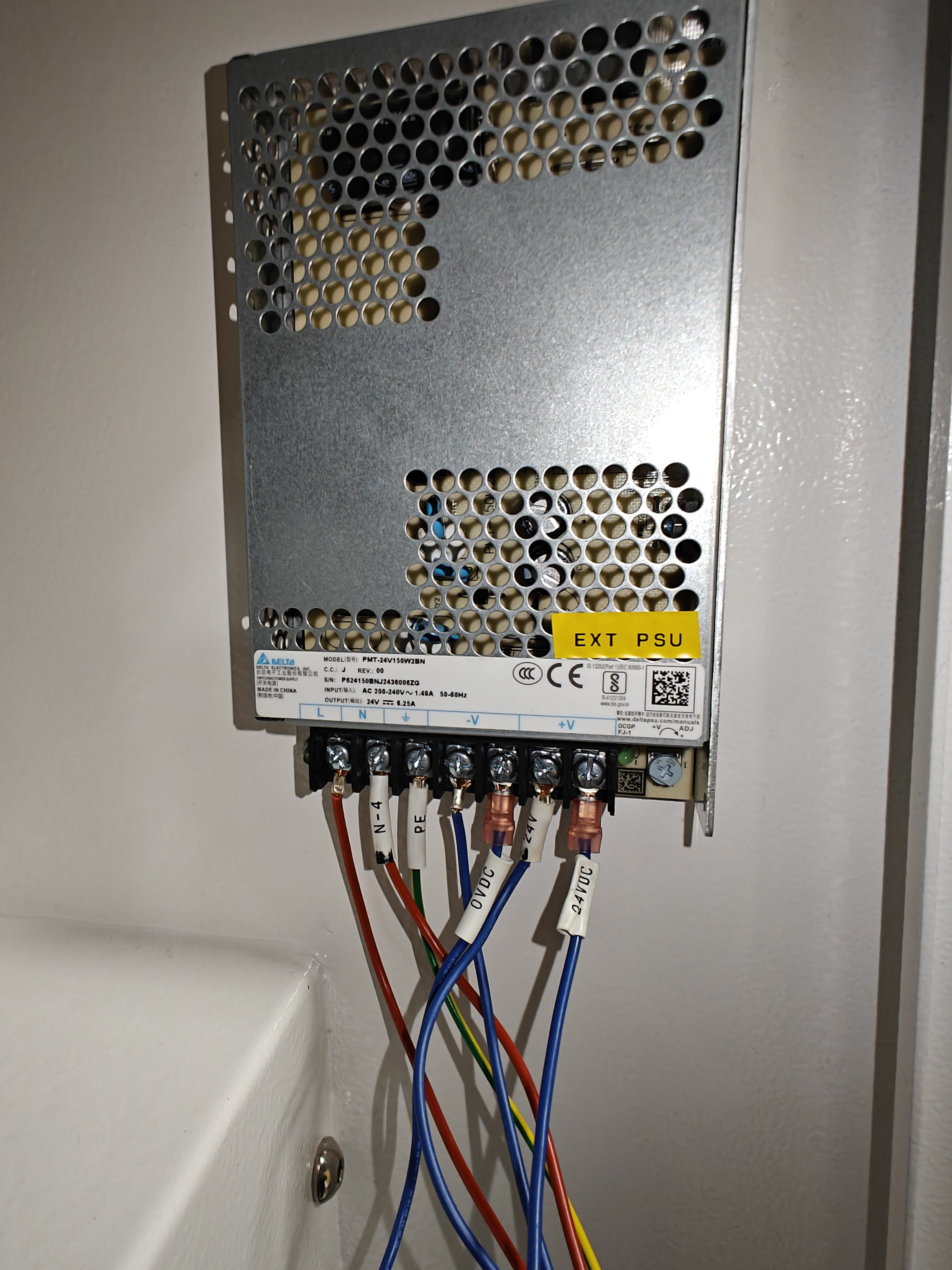
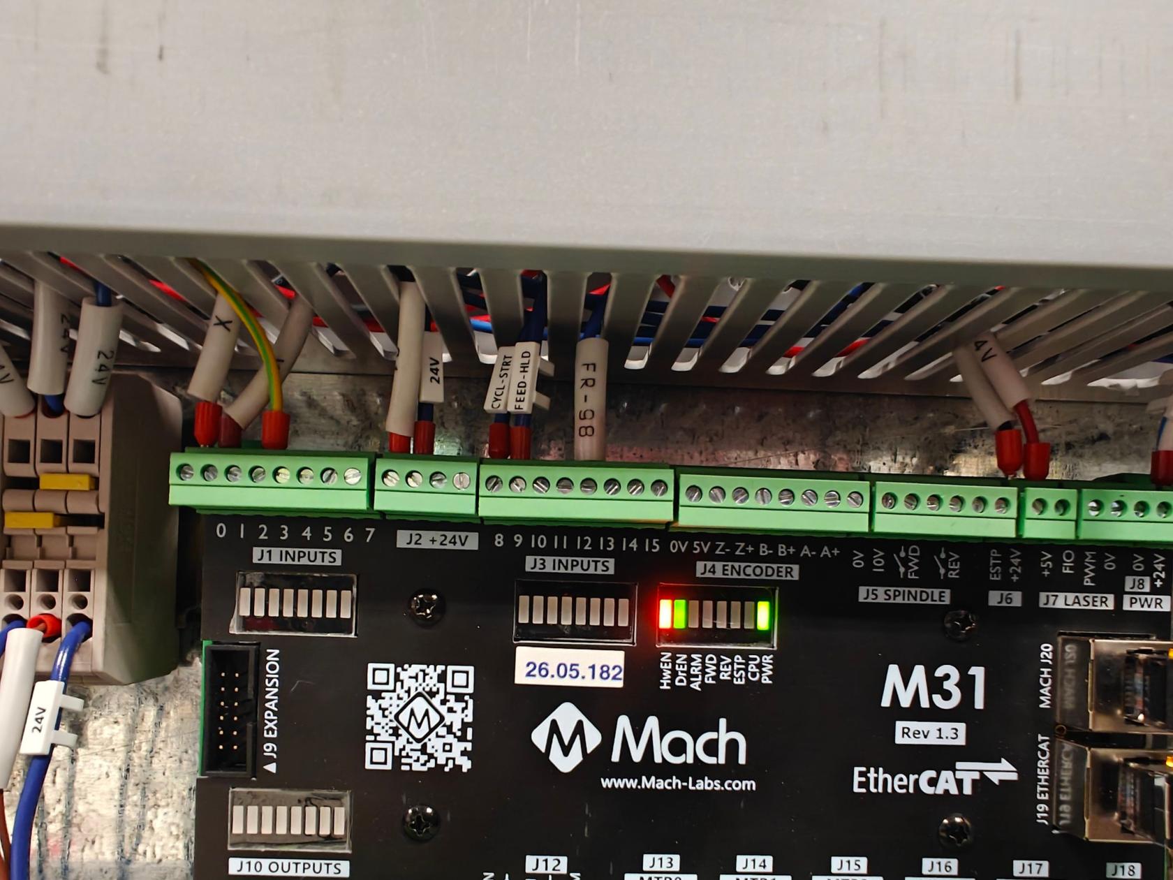
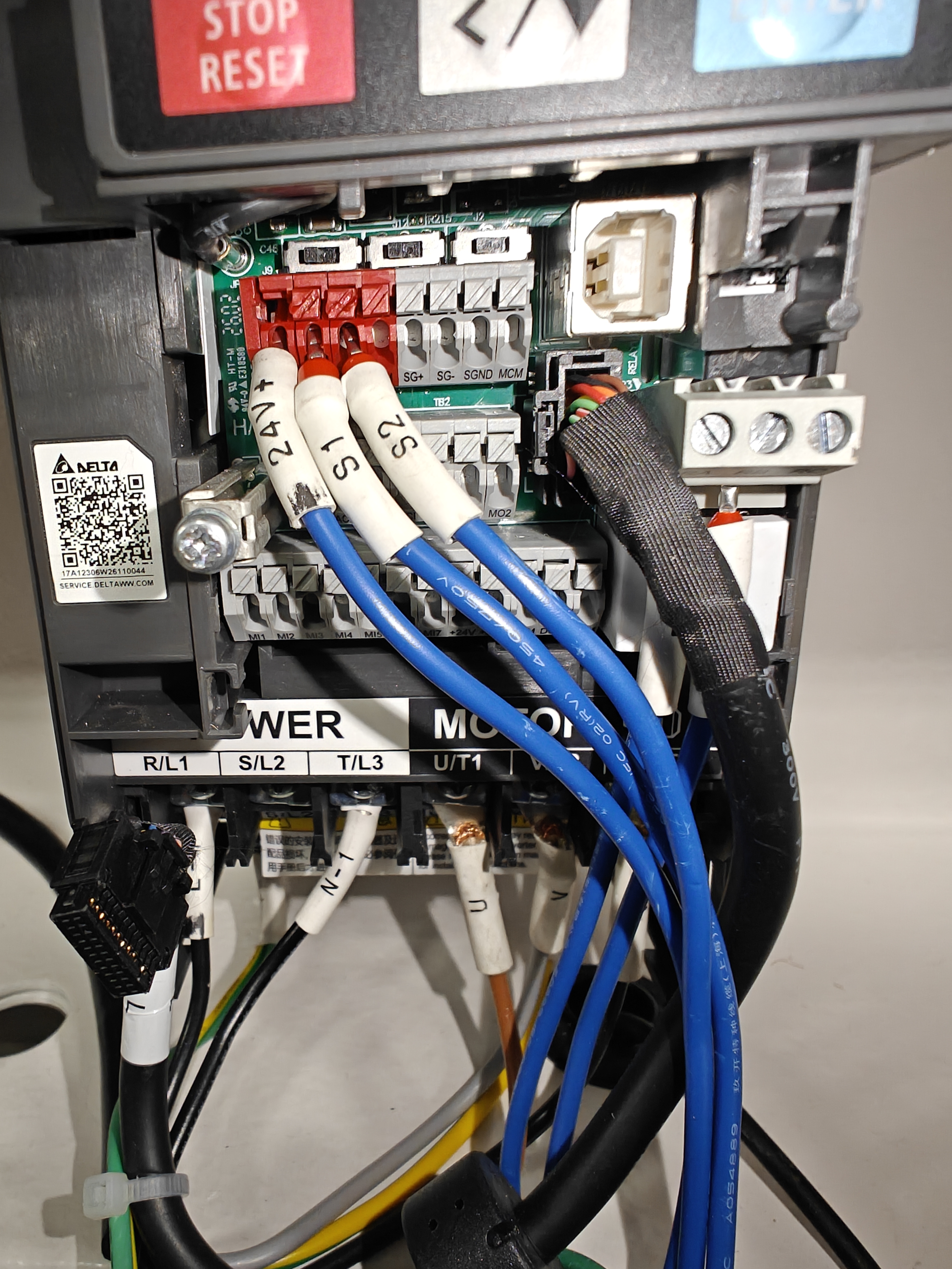
Spindle Wiring as shipped from the factory:
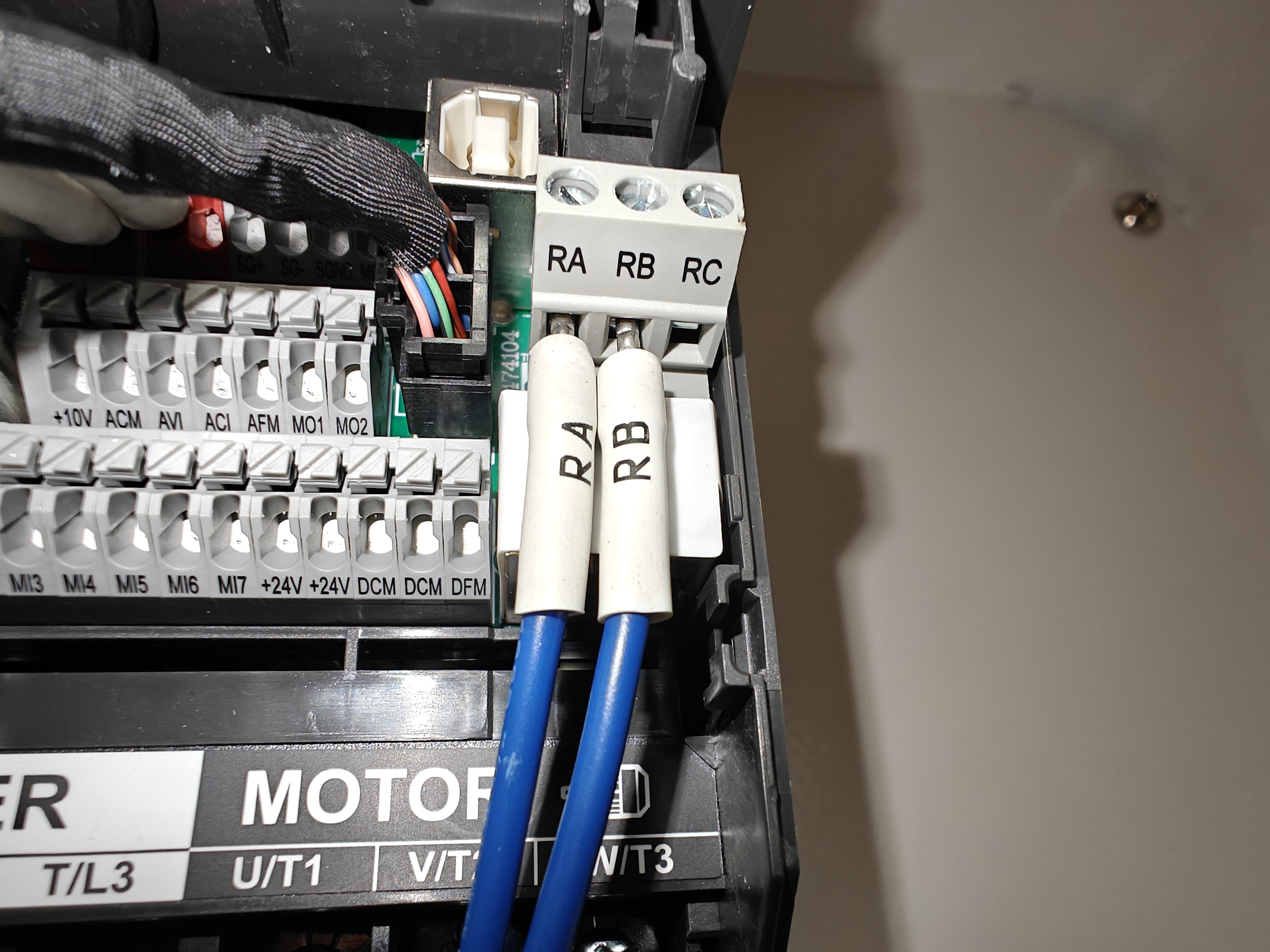
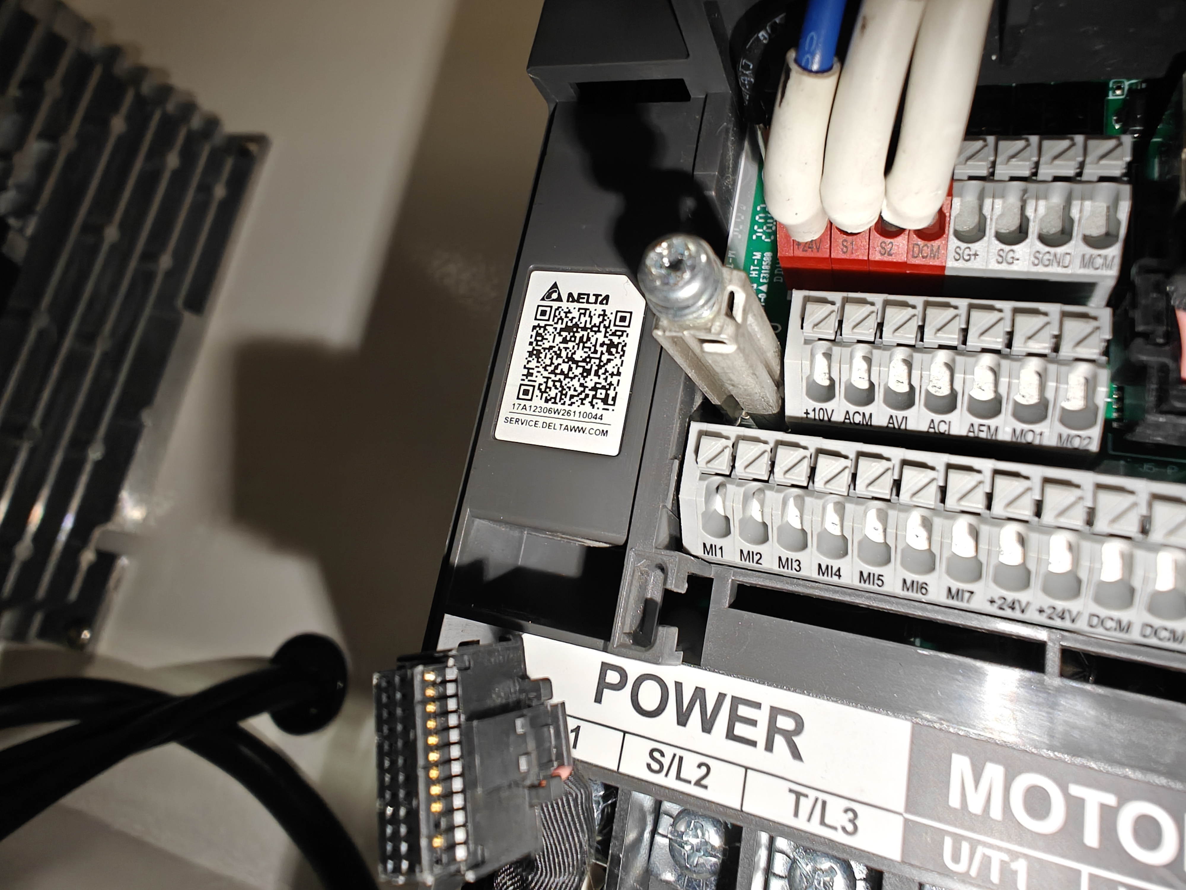
3. HMI Buttons and Screen Install
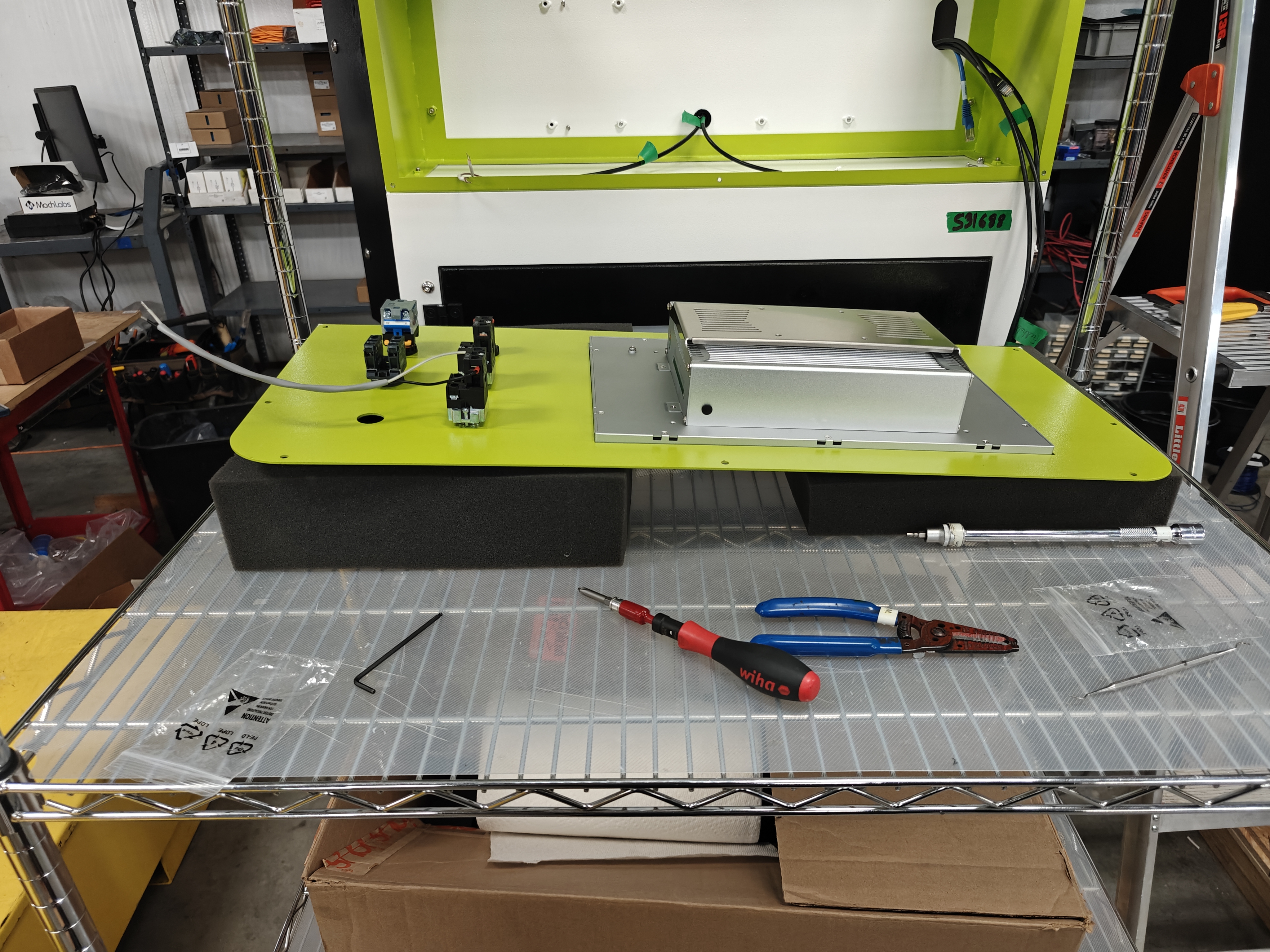
Remove the small labels. We will need to pull the face plate and put an overlay on it. Take the buttons off and remove the screws, then put the screws back in the holes once the cover is off so that we don't lose the screws.
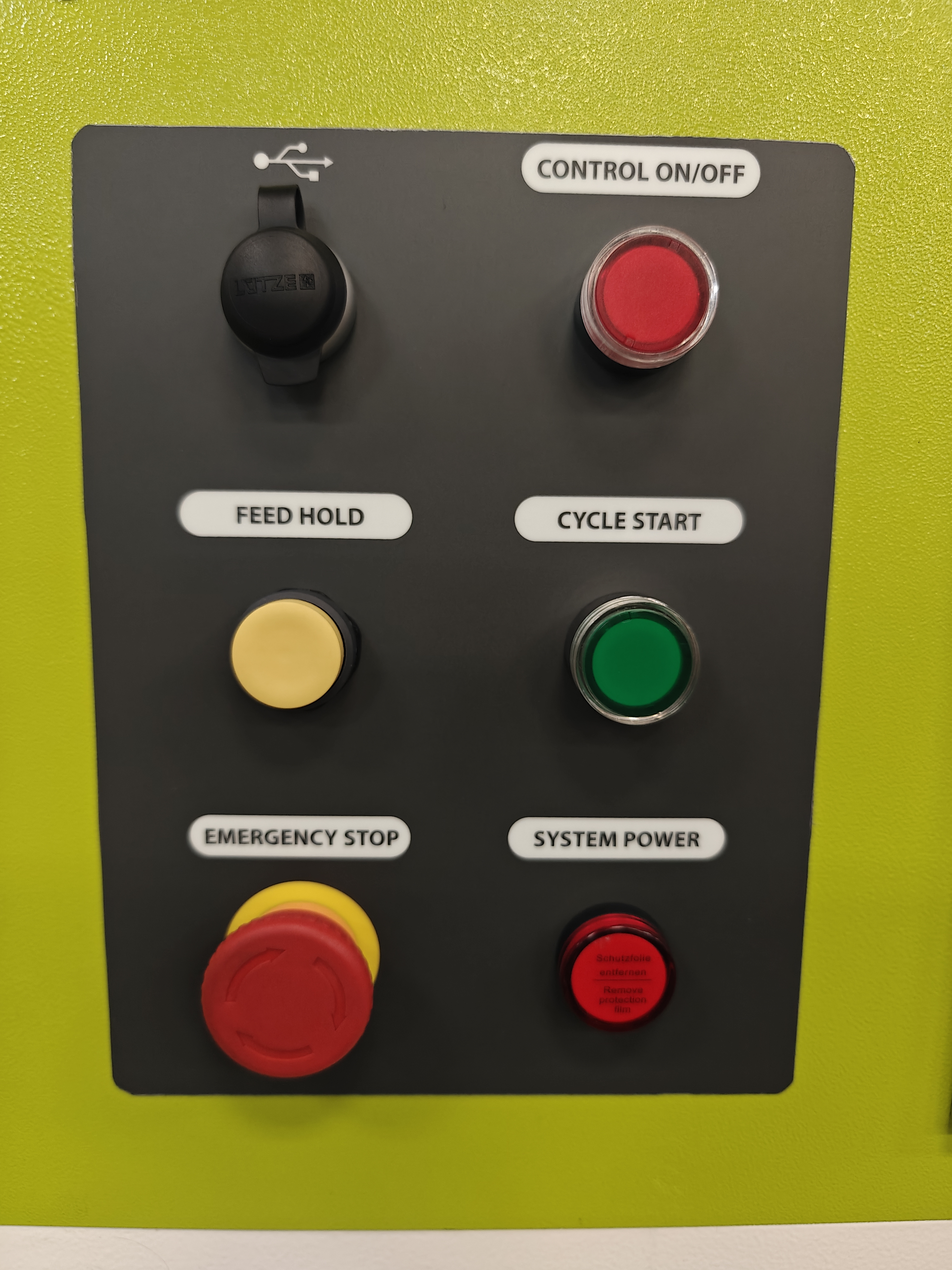
Put in the USB Plug in where the USB symbol is on the faceplate. The control on/off button should be a red one that is momentary, do not use a toggle switch. The Feedhold button should be yellow, we will provide this one. The System Power button should be a green one. The Estop button should be the big red one. System Power is a red LED on indicator.
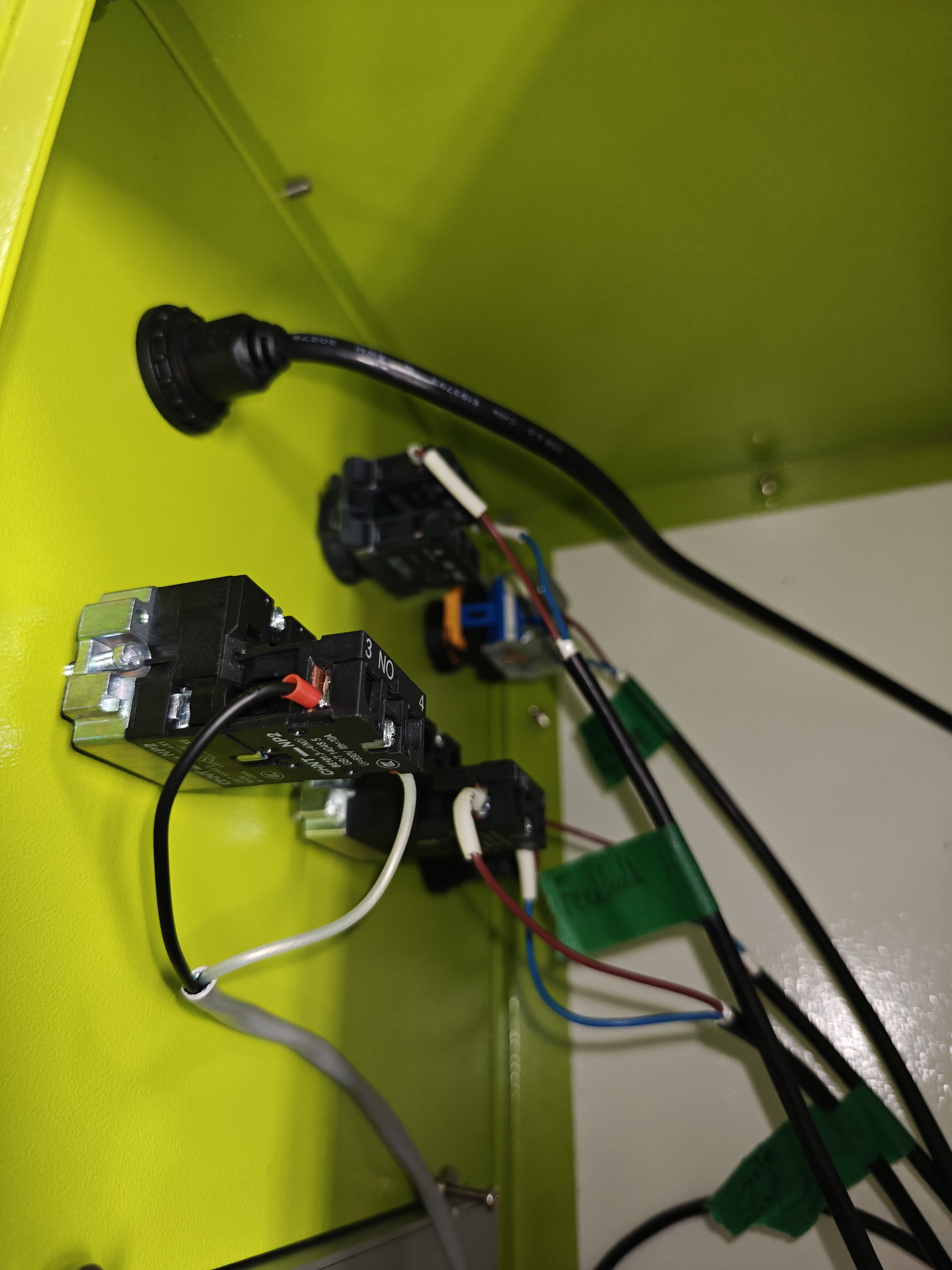
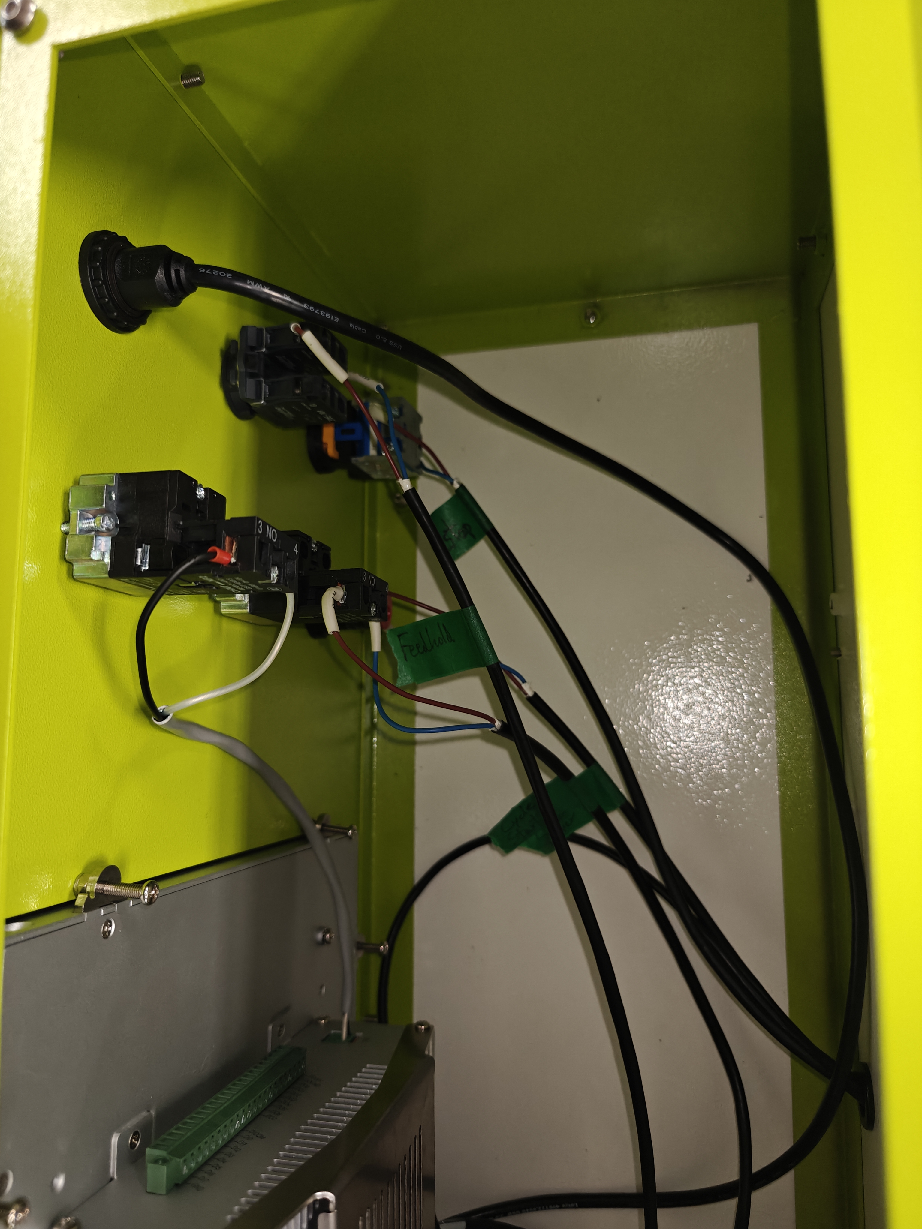
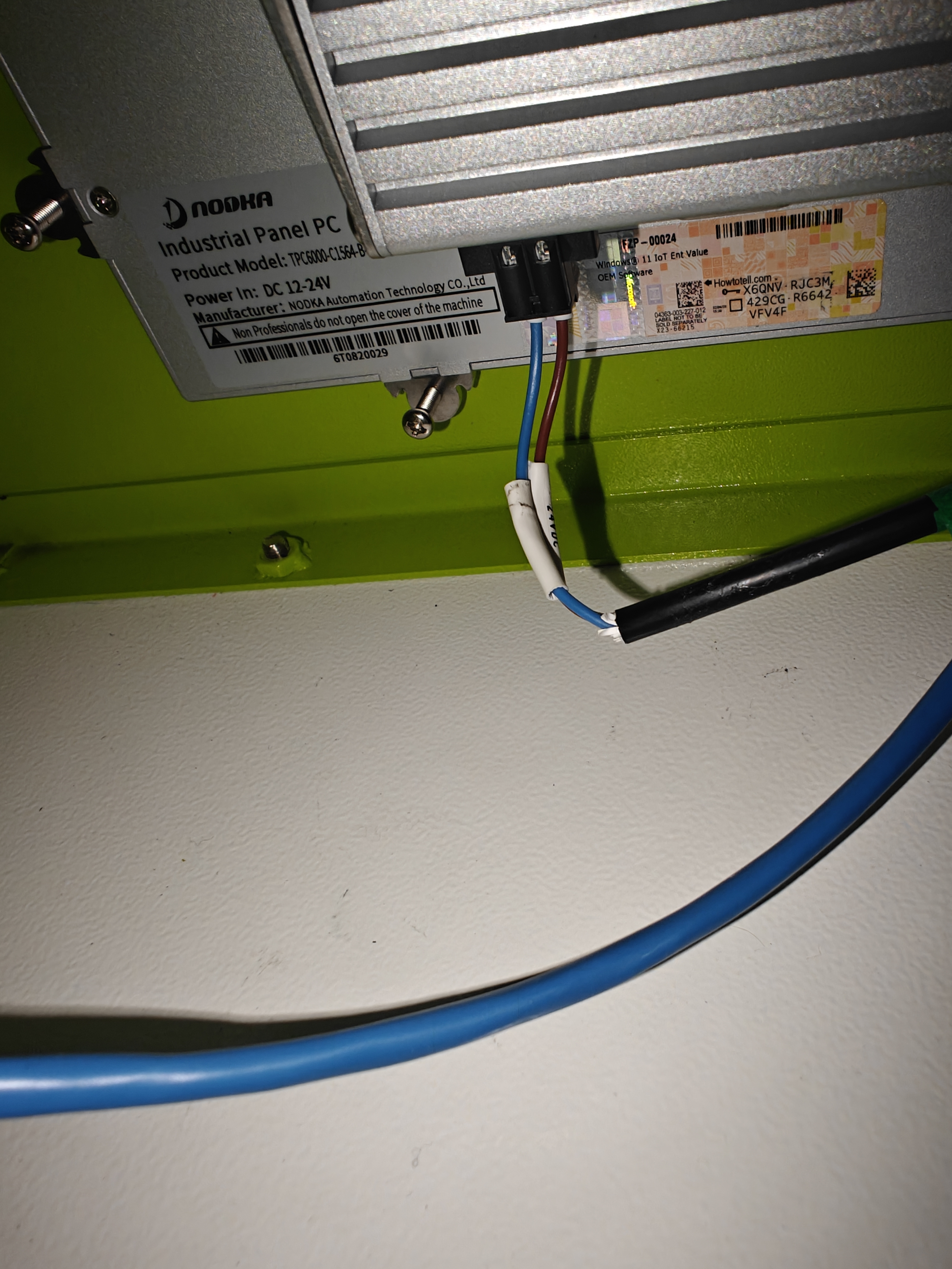
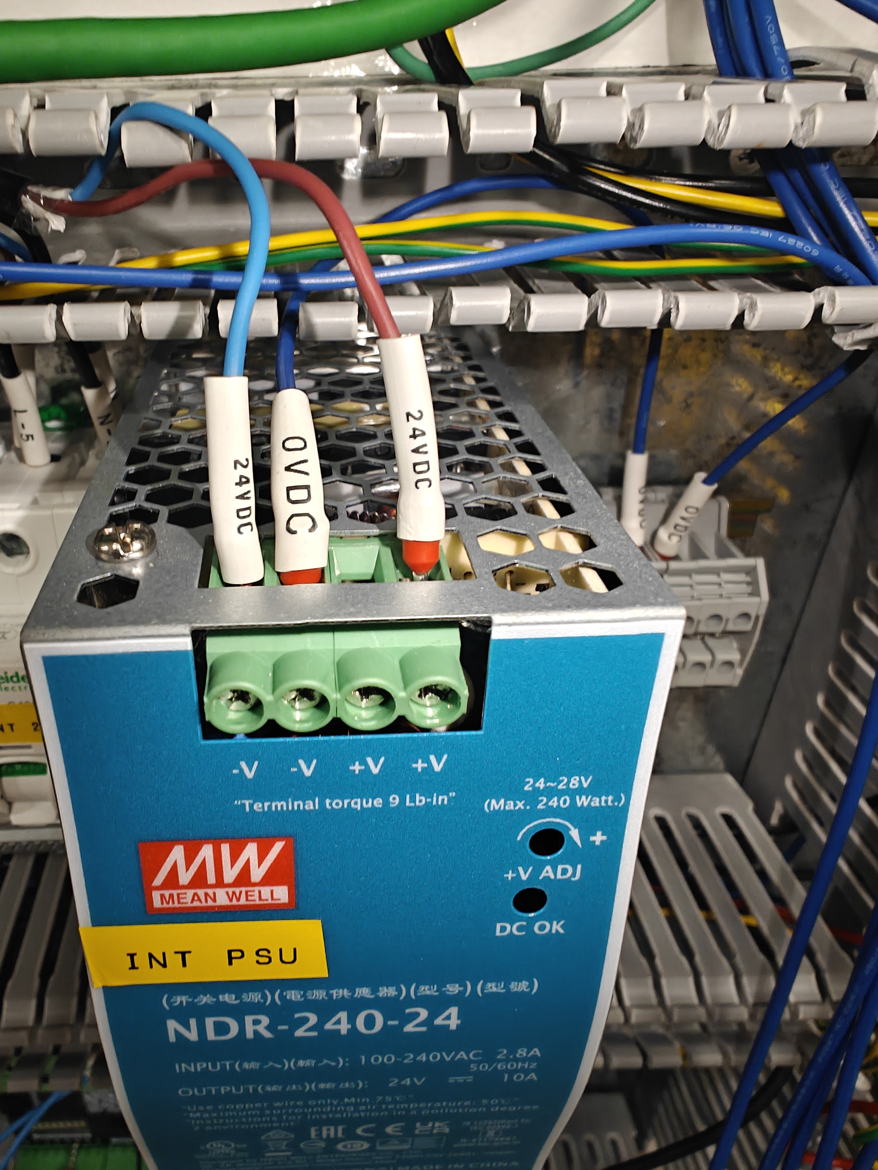
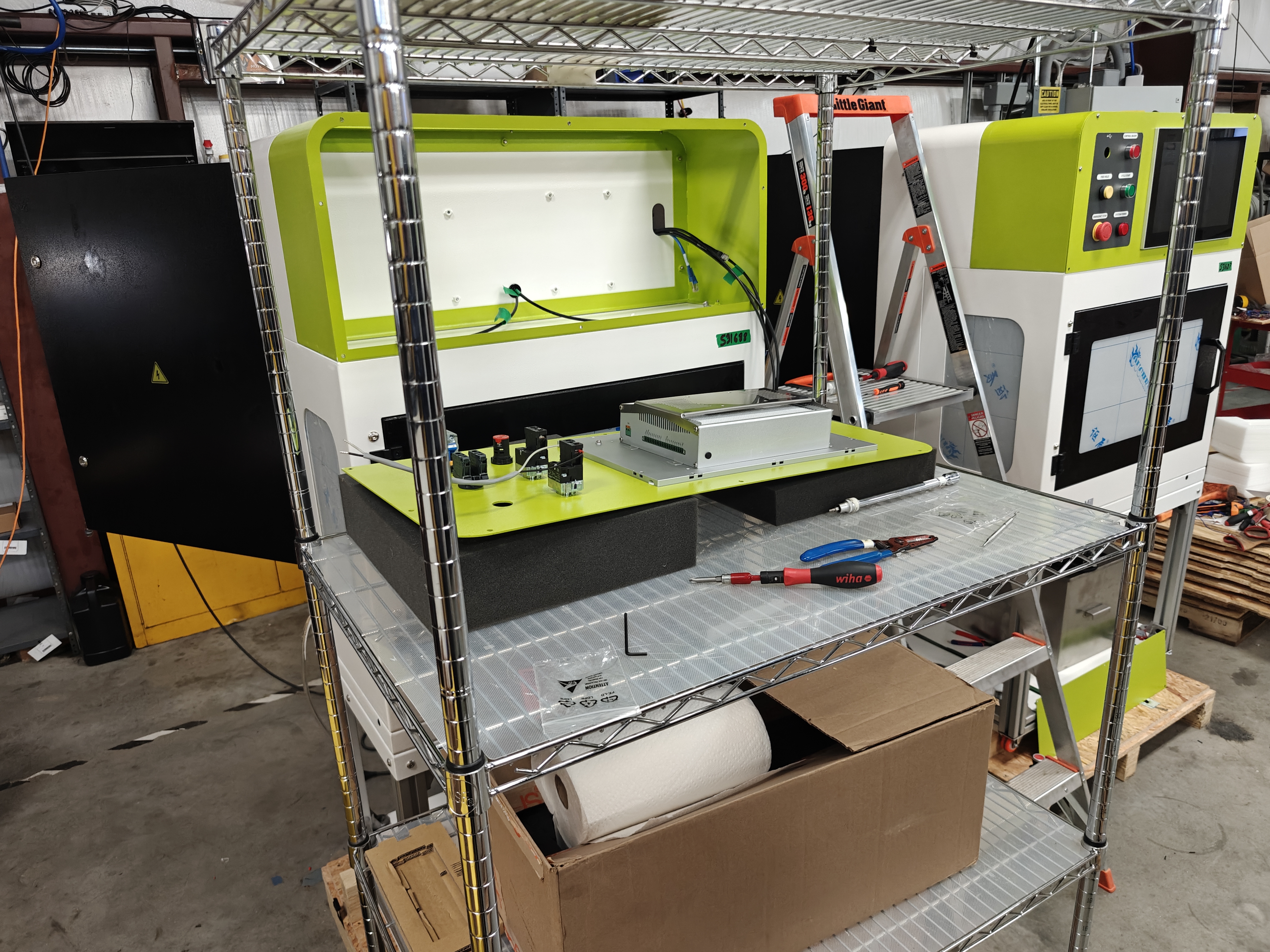
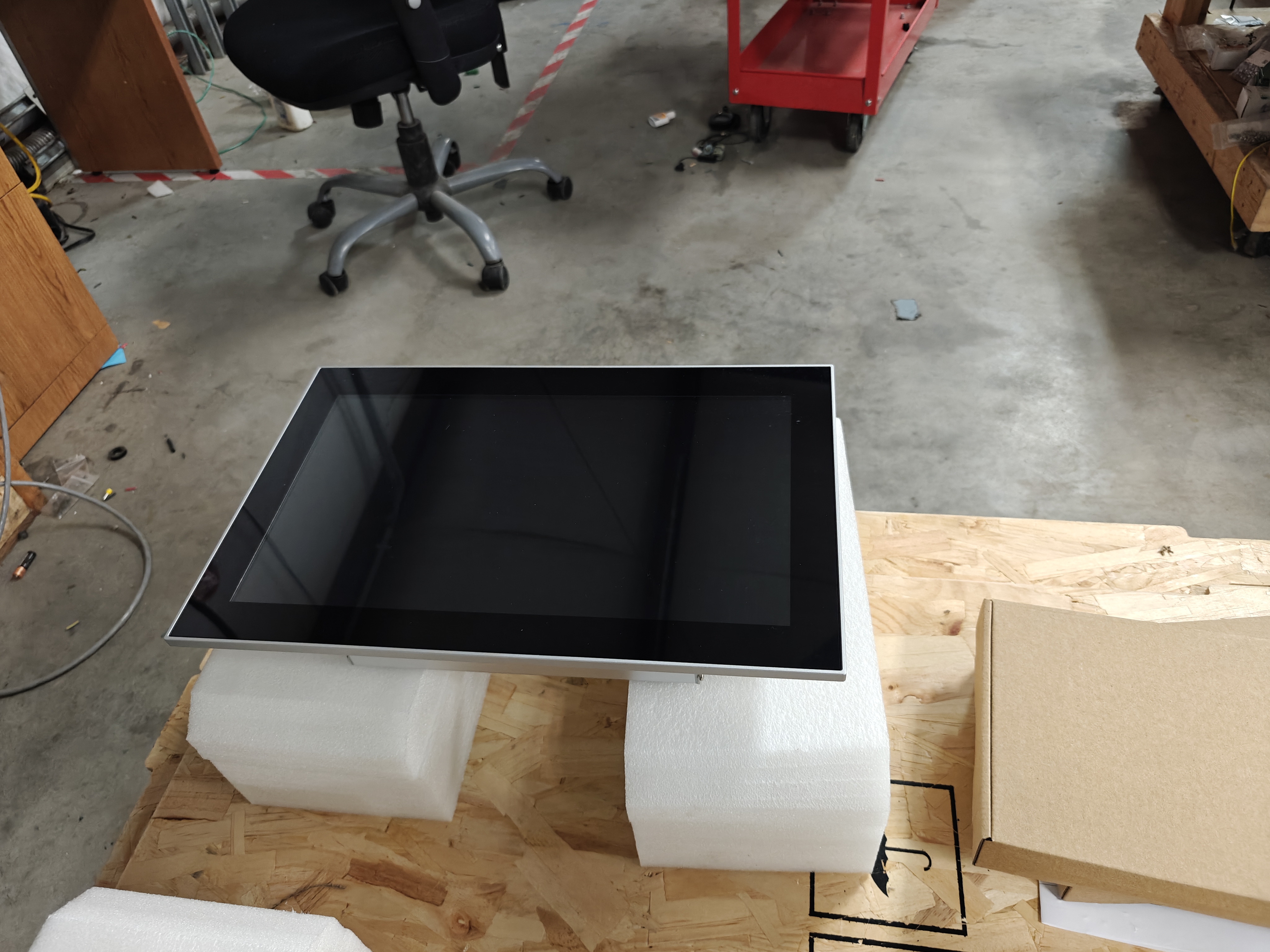
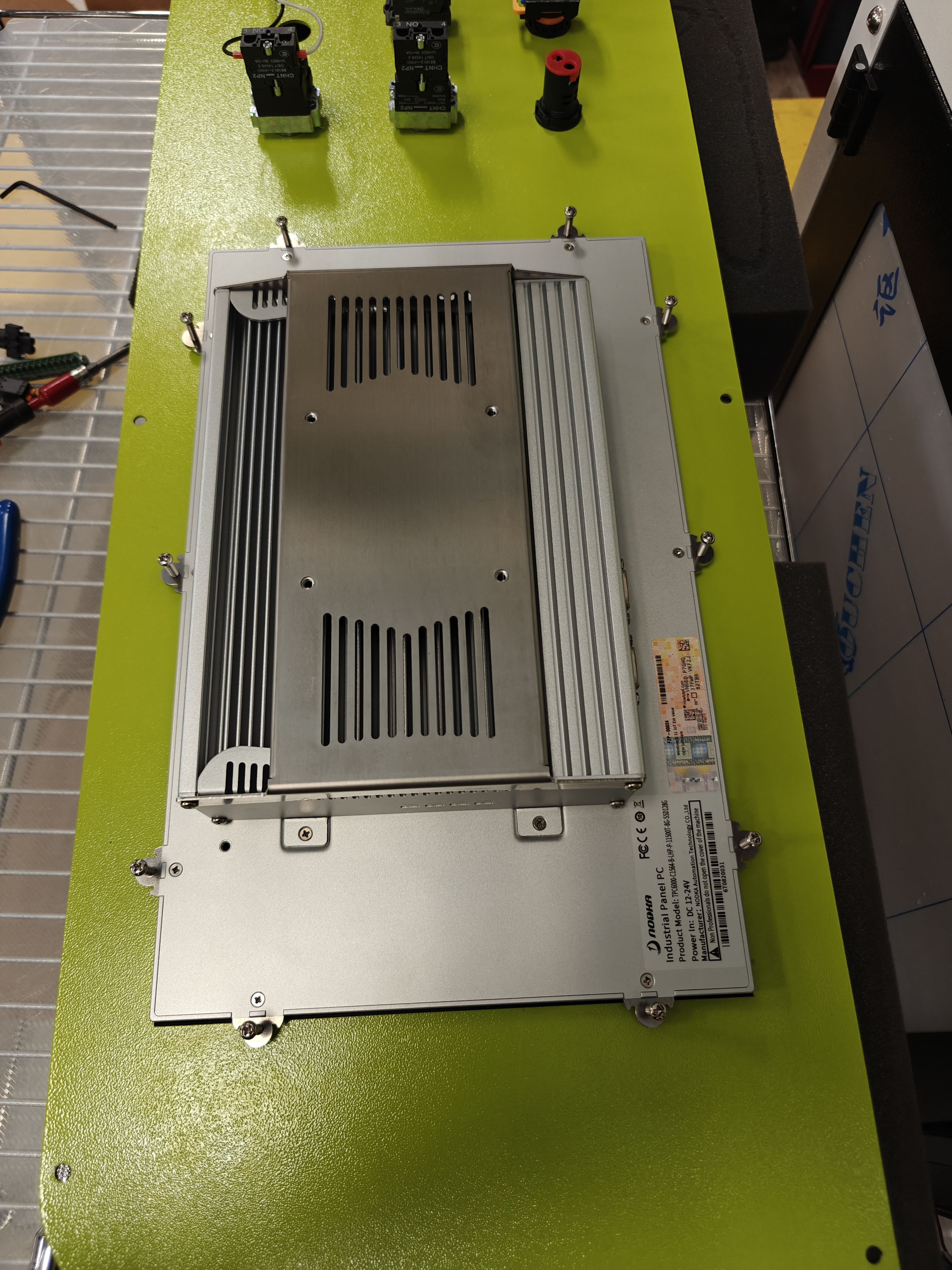
Run one of the provided cables between the Int Power supply and the uppper Phoenix connector on the PC. Polarity is very important on this connection.
On the INT PSU, run the Brown wire to +V, run the Blue wire to V-. On the PC Connector side, run the Brown wire to the side marked on the PC with a +, run the Blue wire to the side marked on the PC with a -.
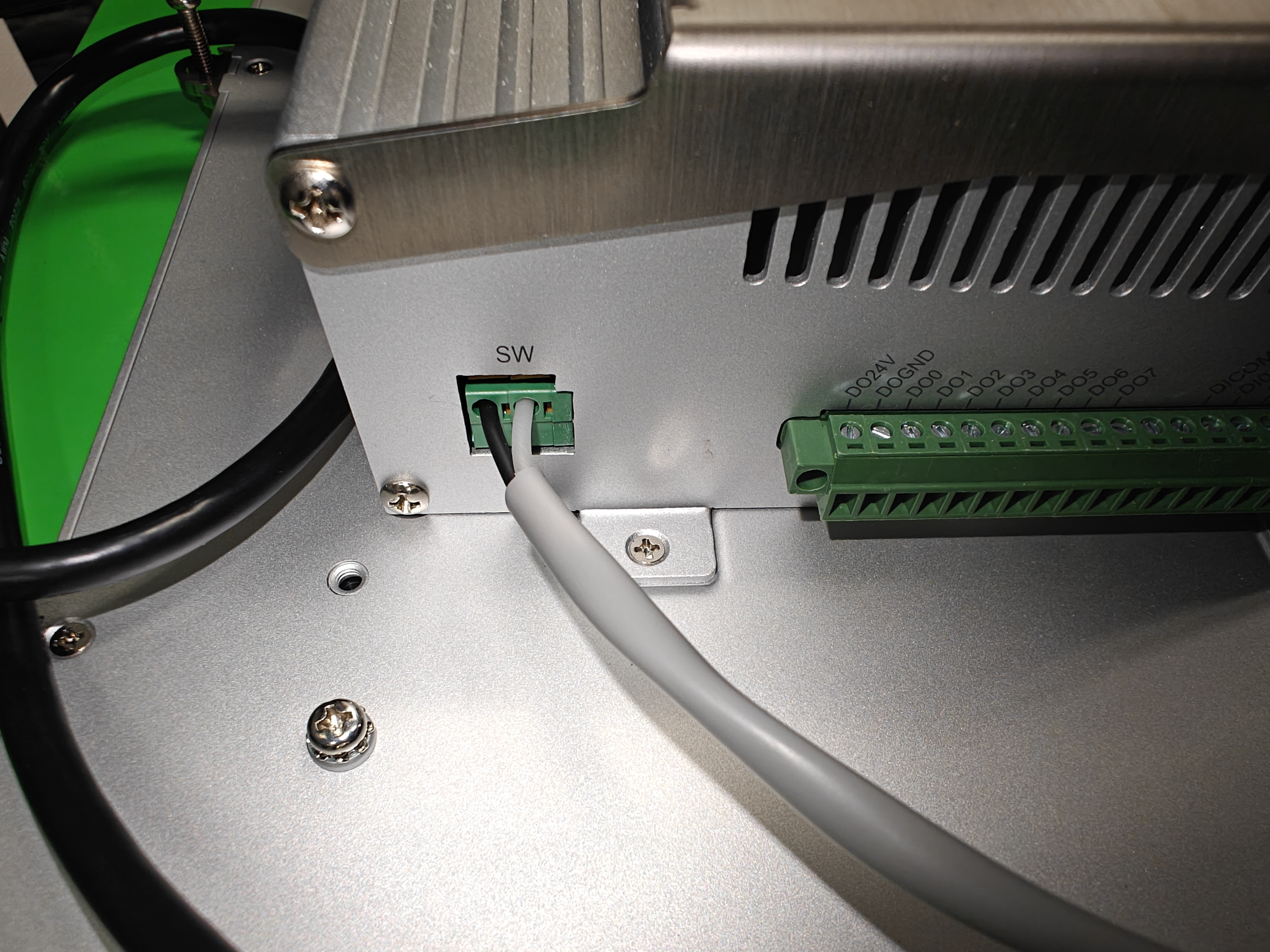
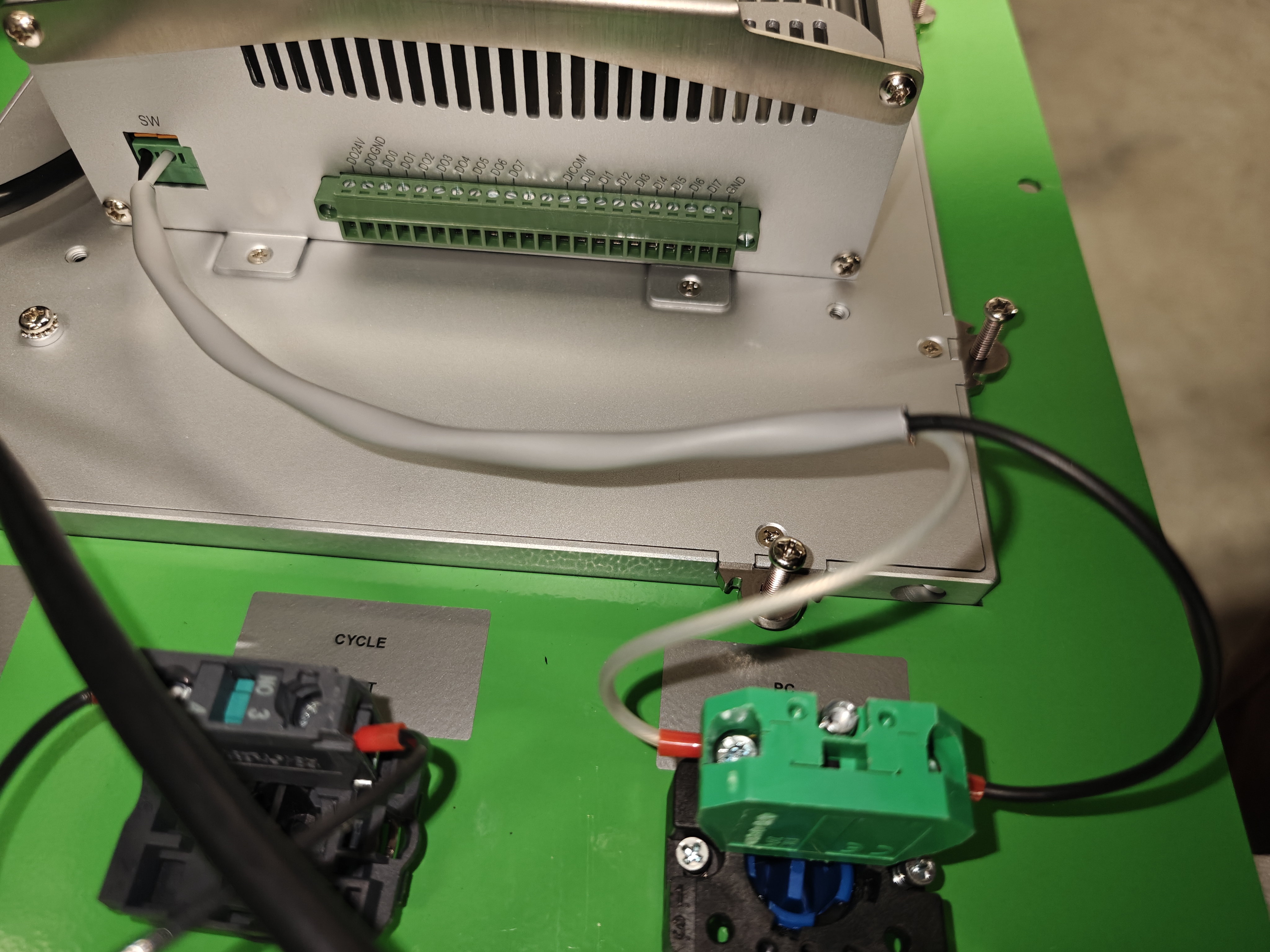
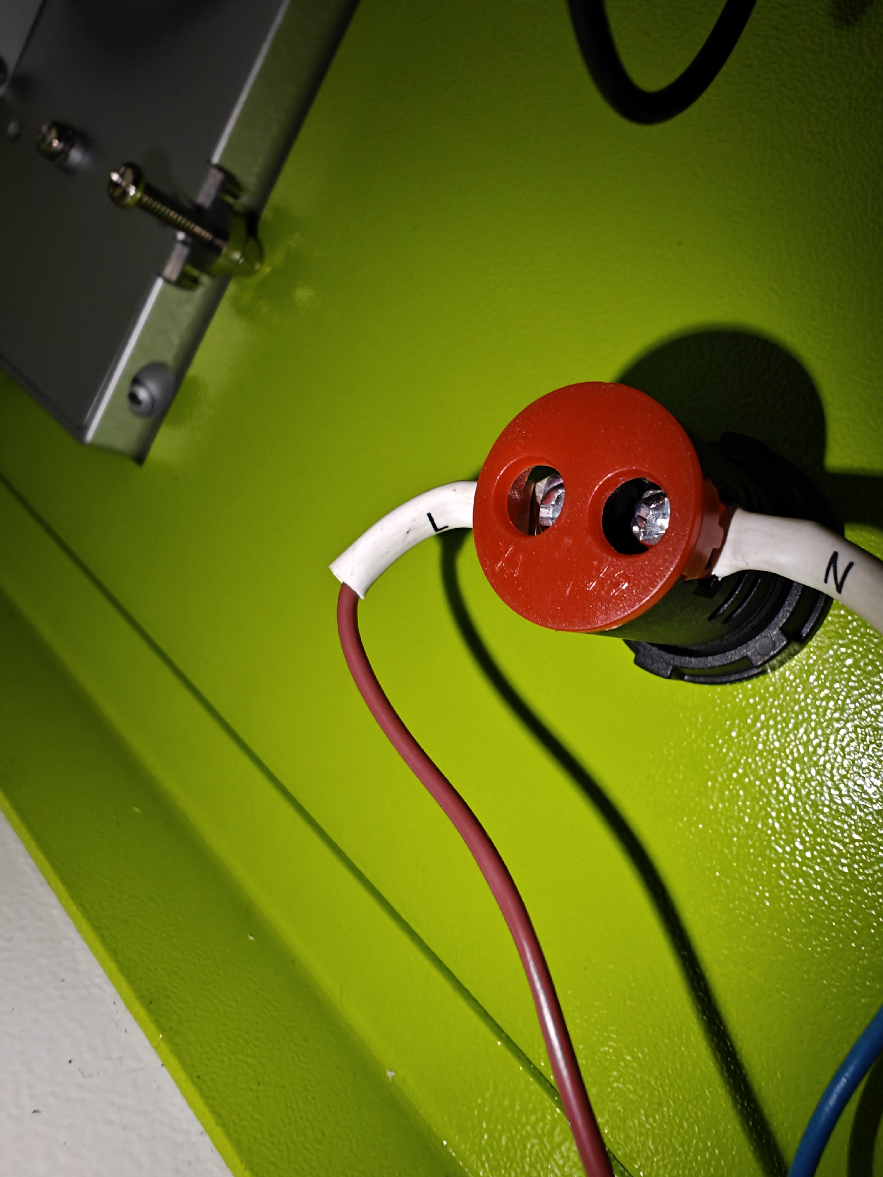
Run a 18AWG 2Conducter cable between the PC Power switch and the PC port as pictured.