Tool Setters and Offsets
Creating a Tool Setter
Open the Calibrate Tool Setters window. Found on the Tools tab.

Creating a Manual Tool Setter
|
|
|
|

To-
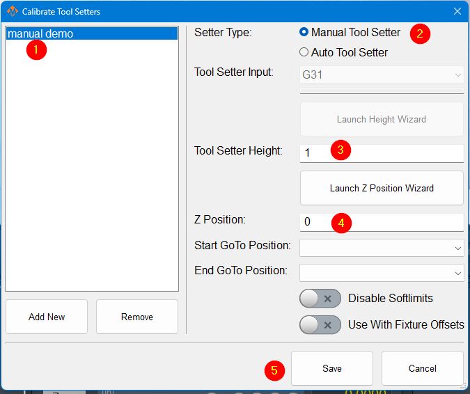
In the Tool Setter tab, click Add New to create a new
manualtool setter.-
Each tool
setter, press 'Add New'. All tool setterssetter must have a uniquename.name. -
After naming
the tool setter,it, select it from thelist,listandtothedisplay its settingsfor that tool setter will be shownon the right-hand side.
-
SelecttheUnder
setterSettertypeType,toselectbeManual.manual.-
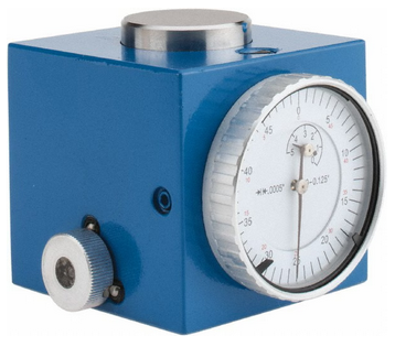
Measure the height of
your setter, and enter it into the Tool Setter Height field. The Z position forthe tool settershouldandbeenter the value in the Tool Setter Height field.-
Set the Z Position.
-
For a fixed-mounted setter, use the Z Position Wizard to determine the machine coordinate for the top surface of the
toolsetter.setter is sitting on. Ifthe tool setter is permanently mounted and the Z position does not change, the Z position wizard can be used to determineOnce this
number. Once itvalue is set correctly, it will not need to be changed.Set-
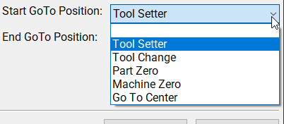
GoTo positionso that the spindle will always go to the setter before touching off.If the setter is mounted outside
ofthe soft limits,toggleenable'DisableSoftlimits'Softlimits. If the tool setter is used in random locations, or the table height changes, then set the Z position to 0.0 and leave the GoTo positions blank.
a -
-
(Optional) Set a GoTo Position.
-
Define a position so the spindle can safely move to the tool setter before touch-off.
-
This ensures a consistent approach and reduces the risk of crashes.
-
-
For randomly placed setters or variable table heights, set the Z Position to 0.0 and leave all GoTo fields blank.
-
This indicates that the setter position may change between uses.
-
-
Click Save to apply and store the configuration.
Once the Z position and height are calibrated, the system will automatically use these values for all tool length offset calculations.
-
Using a randomly placed tool setter

-
Remove all tools from the
spindle,spindle.and-
off-
If the
manual setter or gauge blocks. If yourspindle uses tool holders or collets, insert an empty holderinto the spindlewhile setting the Z position.
-
touch -
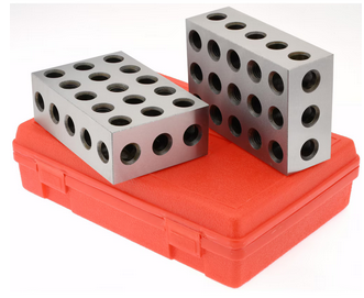
ClickPlace the
SetmanualPositiontoolbutton.setterThisorwillgaugeuseblocks on thepositiontable at the desired location.-
Carefully jog the spindle down until the tip touches the surface of the
tipsetter.of
your-
-
Click Set Position.
-
-
This sets the Z position based on the current spindle location and the entered height of
your setter to settheZtoolposition.setter.
-
-
-
Insert and measure each
oftool required for thetoolsjob.you-
-
Perform a tool measurement cycle for
thiseachjob.tool to record its length offset
-
need -
Creating an Auto Tool Setter
 |
|
-
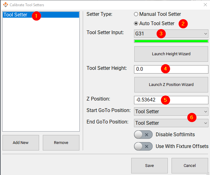
Click Add New to create a new tool
settersetter.with-
Enter an appropriate name for the tool setter.
-
-
Set the Setter Type to Auto.
-
Select the
setterProbetypeInputto be auto. Selectthat theprobe input thetool setter is wired to.-
The indicator bar below the input selector will turn green when the tool setter is triggered.
You, -
a helper, can manuallyManually trigger the setter (or have a helper do so) to confirm
that you havethe correctinput.input is selected.
or-
-
If the tool setter height is known,
itsenterheighttheshouldvaluebeinentered.the Tool Setter Height field.-
If the
tool setterheight isnotunknown,known,clicklaunchLaunchtheHeightheight wizardWizard and follow the on-screen instructionsfortomeasuring.measureThisit.will -
theThe tool setter
tomust be wired to thecontrol.control for this process.
require -
TheSet the Z
positionPositionforto the machine coordinate of the surface where the tool settershould be the machine coordinate for the surface the tool setter is sitting on. The Z position wizard can be used to determine this number if it is not known. If the tool setter is randomly placed, not fixed, then this value will be set to 0.0 here, and will be set each time before you begin measuring tools. See the instructions above:Using a randomly placed tool setterOptionally, select goto positions to be associated with this tool setter.rests.Selectinga position will cause the machine to go to that position before touching off with this setter. That works very well with a permanently mounted setter.If the position is unknown, use the Z Position Wizard to determine it.
-
For a randomly placed setter, set the Z Position to 0.0. This value will be defined each time before measuring tools.
-
See also: Using a Randomly Placed Tool Setter.
-
(Optional) Define GoTo Positions for the tool setter.
-
Selecting a GoTo position allows the spindle to move automatically to the setter before touching off.
-
This is recommended for permanently mounted setters.
-
If the setter is located outside
ofthe soft limits,turningenableonDisable'disableSoftlimits.softlimits'
willbe needed to reach the setter. -
WithaFor randomly placed
setter,setters, leavetheseall GoTo Position fields blank.Either-
Manually jog the spindle to the
setter,setter ormoveplace the settertobeneath thespindle.spindleWhenasyouneeded.begin -
process,The
theremachine willbenotnoperform automaticjogging.jogging during this process.
the-
Creating a Tool Setter Go-To Position
This is documented in Modifying GoTo Positions
Align Tool Edge to Center of Tool Setter
-
ThisEnable the featurewillbyposition the edge of the tool to the center of the tool setter. To begin using this feature set the parametersetting Tool Setter Align Tool Edge To Setter to -
configureConfigure the
parameter "Tool Setter Align Tool Edge Offset"andparameter.choose-
Choose between
using "ToolRadius"Radius or"Tool SetterOffset"Offset as the source for the offsetneededused to align the tool edge to the center of the setter.
Lastlychoose -
-
Select the Offset Direction to define which
directionwaytotheoffsettool moves when aligning thetooledge to thecenter.center of the setter.
This feature positions the edge of the tool precisely at the center of the tool setter, ensuring accurate alignment and consistent measurement results.
Configure the following Parameters:
| Parameter Name | Value | Optional Values | Default Values |
| Tool Setter Align Tool Edge To Setter | Yes | No | |
| Tool Setter Align Tool Edge Offset | Tool Setter Offset | Tool Radius, Tool Setter Offset | Tool Radius |
| Tool Setter Align (X or Y) Axis To Setter | X Positive | X Positive, X Negative, Y Positive, Y Negative | X Positive |
Parameter "Tool Setter Align Tool Edge Offset" must be set to "Tool Setter Offset" before the Tool Setter Offset column will show up in the tool table.
View and Edit the
The tool table directly
In the upper left corner of the Tools tab is the Tool Table button
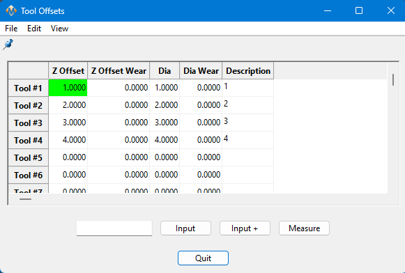
This table can be edited and customized extensively to meet the needs of your system. Please see Tool Offset Table Customization