MachPro Plate Alignment and Transform Functions
{{@2007#bkmrk--1}}
2026-05-05-T09-07 Under construction - adding all of the transform variants.
Plate Alignment
Plate alignment provides a simple way to accurately rotate your work offsets to match the work piece on your table. Often large work pieces are not perfectly square on the table, and this tool solves that problem.
First steps
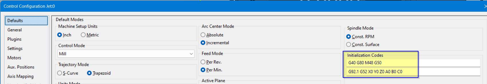
Remove G69 (Coordinate System Rotation Cancel) from the MachPro initialization codes
- Disable MachPro
- Pull down Configure -> Control and select the Defaults tab.

- If the G69 code is in the initialization codes, remove it. Click OK to close this configuration window.
- Remove G69 from the safe start lines of your G-Code files.
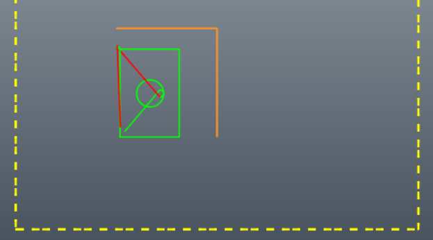
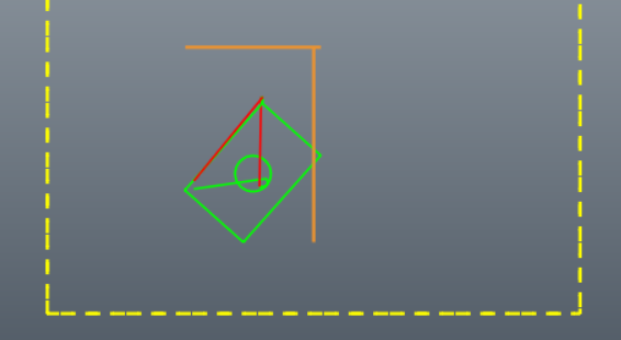
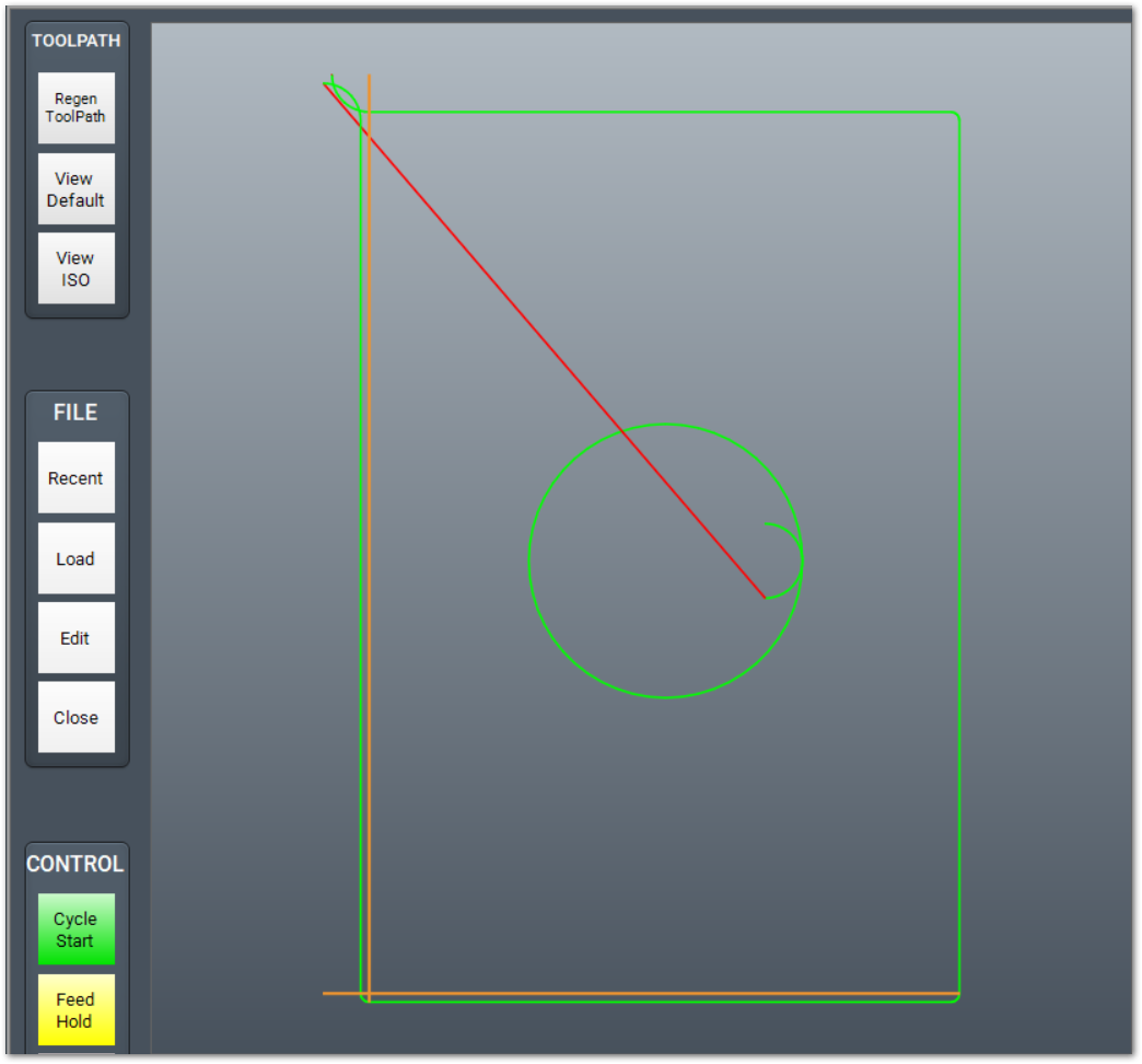
This is an extreme example of using plate alignment on a work piece that was rotated almost 45 degrees on the table.
|
|
|
|
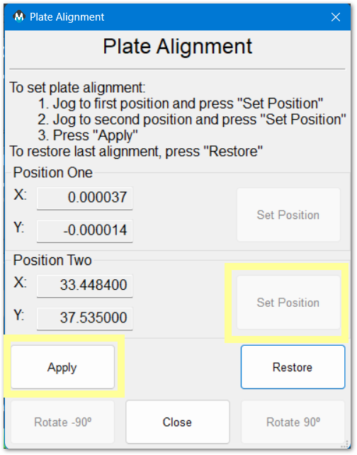
Using Plate Alignment
- Ensure that the machine has been homed, either through absolute encoders, or your startup homing process. Your DRO will show black axes labels.
- Load your G-Code file
- Enable the machine and jog to a position along one edge of the work piece - near the one end. Touch your tool to the edge of the work piece
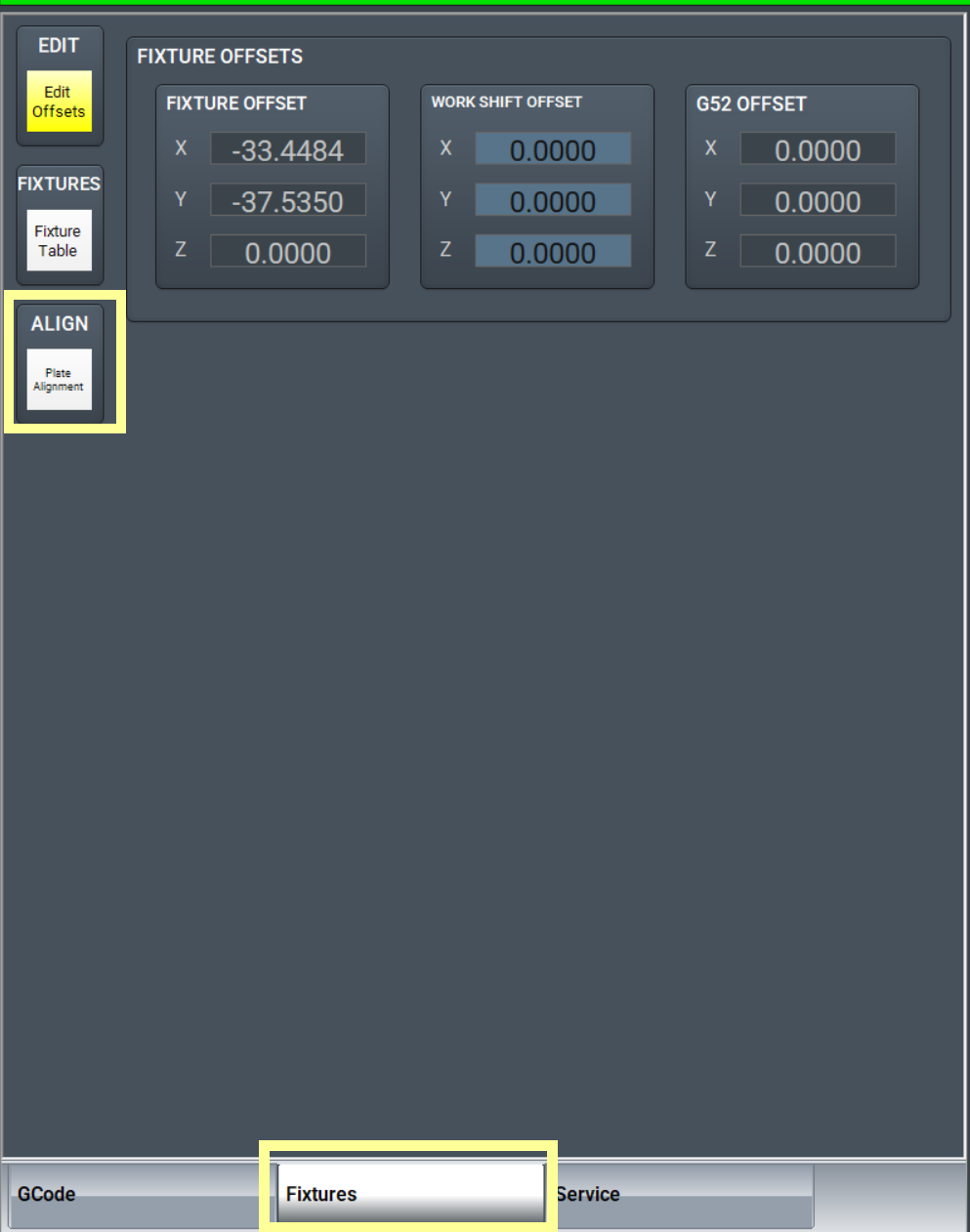
- Go to the Fixtures tab, and click the Plate Alignment button.
- Click the first Set Position button
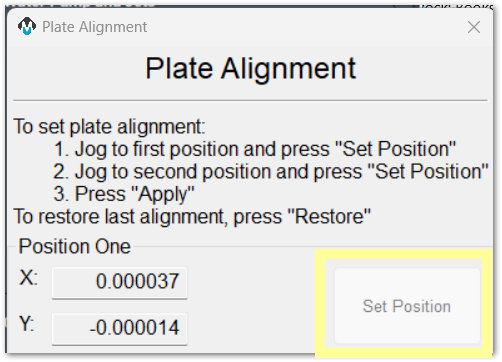
- Jog to a second position further along the same edge of the work piece, and again touch the tool to the edge of the work piece. Moving approximately 1 yard or 1 meter from the first position should provide good angle measurement accuracy.
- Click the second Set Position button

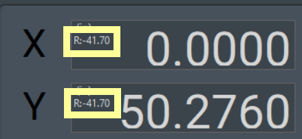
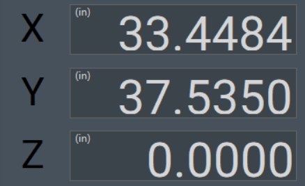
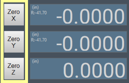
- Click Apply. The rotation will be applied to your part offset. Your tool path on the screen will be updated, and the DRO will indicate the angle of rotation that has been applied.
- Confirm or set your part zero with the Fixtures tab
- Run your job normally. MachPro has rotated the cut path to match the angle of the edge of the work piece.


Cancel Plate Alignment
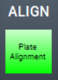 Click the green Plate Alignment button and the rotation will be removed.
90 Degree Rotation
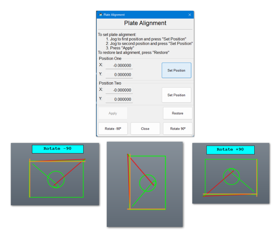
This is useful for simple rotations. If you want to change the rotation close the Plate Alignment app, then cancel rotation by clicking on the green Plate Alignment button again. The rotation will be canceled and all settings will revert to normal.
Plate alignment application notes
Both G68: Coordinate System Rotation and G69: Coordinate System Rotation Cancel are modal commands, and can interfere with each other. It is best to only use them at the beginning of the blocks where they are to take effect. The G68 command is used as part of the plate alignment process and a G69 command in the initialization or safe start codes can cause the plate alignment to be canceled.
Transform Functions
The
What transform functions aredo
Transform tofunctions be configured as widget buttons. (Documentation for widget buttons) The easiest buttons to configure are underchange the axestoolpath DRO. You will need to configureof a functionloaded buttonG-code forfile. eachA Transformtoolpath functionis youthe needpath tothat use.the
There are six transform functions:
- Array
- Mirror X
- Mirror Y
- Rotate 180
- Rotate 90 CCW
- Rotate 90 CW
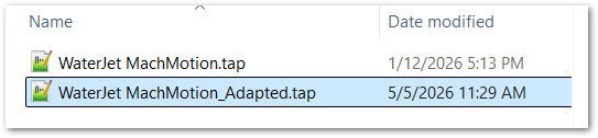
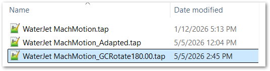
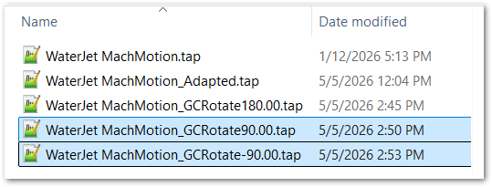
FirstAn loadadapted yourfile is a new G-Codecode output file that MachPro creates from the loaded source file. MachPro loads the adapted file after the transform operation. The source file remains the original file unless you edit it. Array and Mirror operations write to a copy of the file with “_Adapted” added to the filename. The degree rotation functions write to copies of the file with GCRotate180.00, GCRotate90.00, GCRotate-90.00 names.
Before you run a transformed file, make sure that the transformed toolpath is in the correct location for the material, fixture, and machine travel.
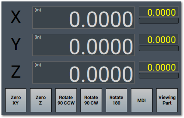
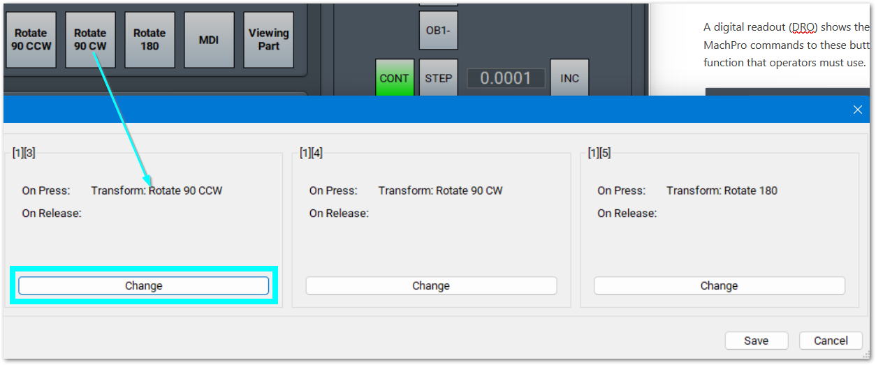
A digital readout (DRO) shows the current axis positions. MachPro has on-screen function buttons under the axis DROs. You can assign MachPro commands to these buttons using the dashboard and widget documentation. Configure a function button for each transform function that operators must use.
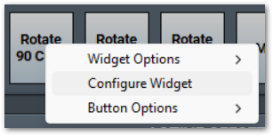
To change the Rotate 90 CCW button, right click on it and select Configure Widget
Locate the widget you want to modify and click on the Change button
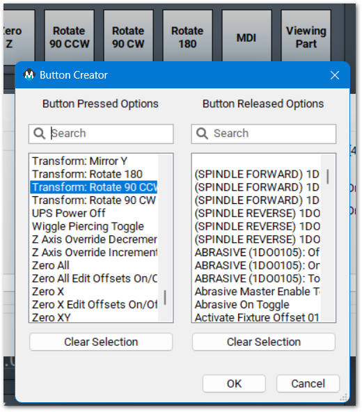
You may either Search or scroll the list of functions. Select the function you want and click OK.
Click the Save button in the lower right corner of the Widget Configuration window
Use a transform function
- Load the source G-code file.
- Click the transform button that you want to use.
- If MachPro opens a settings window, enter the required values.
- Click OK.
- Examine the toolpath preview.
- Make sure that the adapted file is the file you want to run.
- Start the cycle.
If you edit an adapted file, save it with a new name. If you run the same transform again on the same source file, MachPro will overwrite the adapted file.
Array
WhenUse youArray clickto make repeated copies of the Arrayloaded button,toolpath.
- Load
windowthewillsourceopen.G-code file. - Click the button that runs Transform: Array.
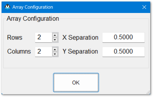
- Enter the number of
rowsrows. - Enter the number of columns.
- Enter the X and Y separation distances.
- Click OK.
- Examine the adapted toolpath.
- Start the cycle when the toolpath is correct.
MachPro creates an adapted array file and loads it. The Array function opens a configuration dialog for rows, columns, and X/Y separation distances. The output path uses the spaceGCAdapter separationsoutput your machine needs, and click OK.settings.
|
|
 |
|
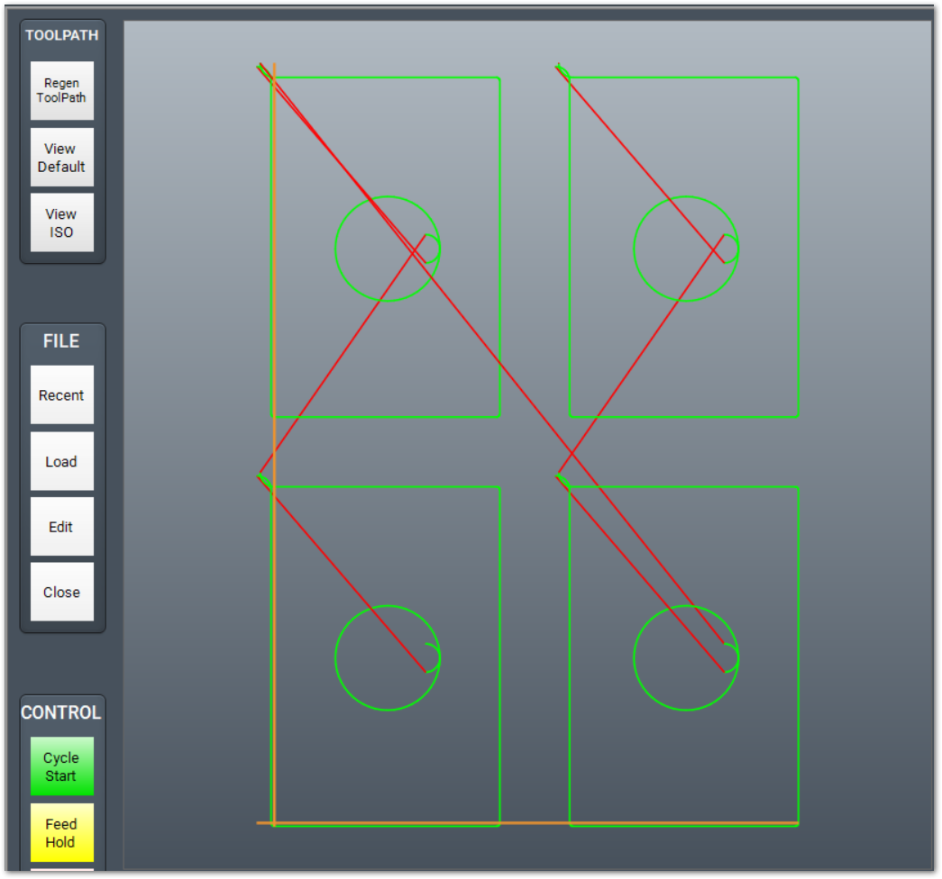
The Array Transform will create a new G-Code file with "_Adapted" added to it. MachPro will run this adapted file when you start the cycle. You may edit the adapted file, but you should save it under a new name. If you run transform array again on the original file, transform will overwrite the adapted file.
Mirror X or Y
TheseUse areMirror twoX separateto functions,make butan theirX-direction effectsmirror areimage similar.of the loaded toolpath.
- Load the source G-code file.
- Click the button that runs Transform: Mirror X, or Mirror Y.
- Examine the adapted toolpath.
- Start the cycle when the toolpath is correct.
Mirror X changes X coordinates to the opposite side of the origin. For example, a feature at X+2 moves to X-2, relative to the origin. MachPro creates an adapted mirrored file and loads it.
Mirror Y changes Y coordinates to the opposite side of the origin. For example, a feature at Y+2 moves to Y-2, relative to the origin. MachPro creates an adapted mirrored file and loads it.
|
Original
|
Mirror X
|
Mirror Y
|
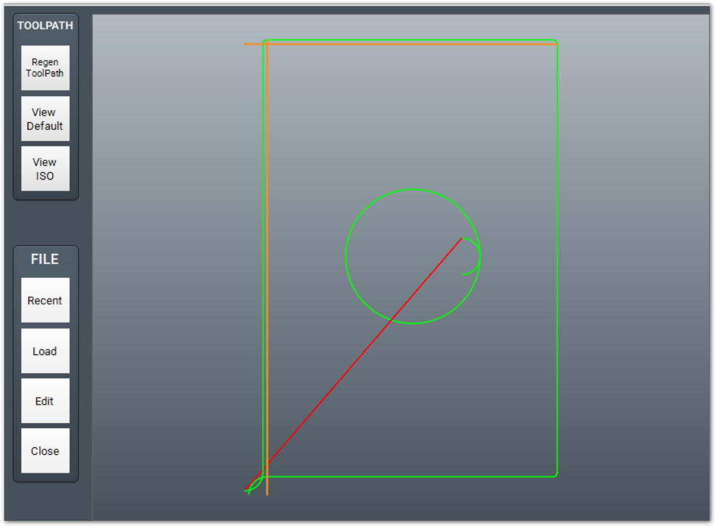
Rotate 180
ThisUse transformRotate process will also write180 to aturn copythe ofloaded yourtoolpath 180 degrees.
- Load the source G-code file.
- Click the button that runs Transform: Rotate 180.
- Examine the adapted toolpath.
- Start the cycle when the toolpath is correct.
MachPro creates an adapted rotated file withand "_Adapted"loads addedit. The Rotate function adds the rotation angle to the endoutput of the file name, and it will continue to write to that file each time you transform the same original file. filename.
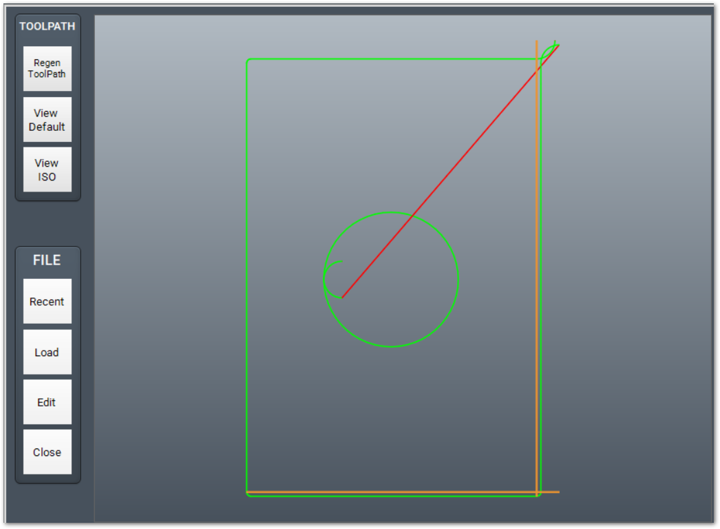
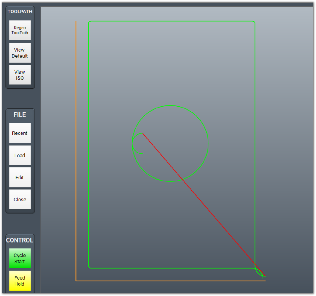
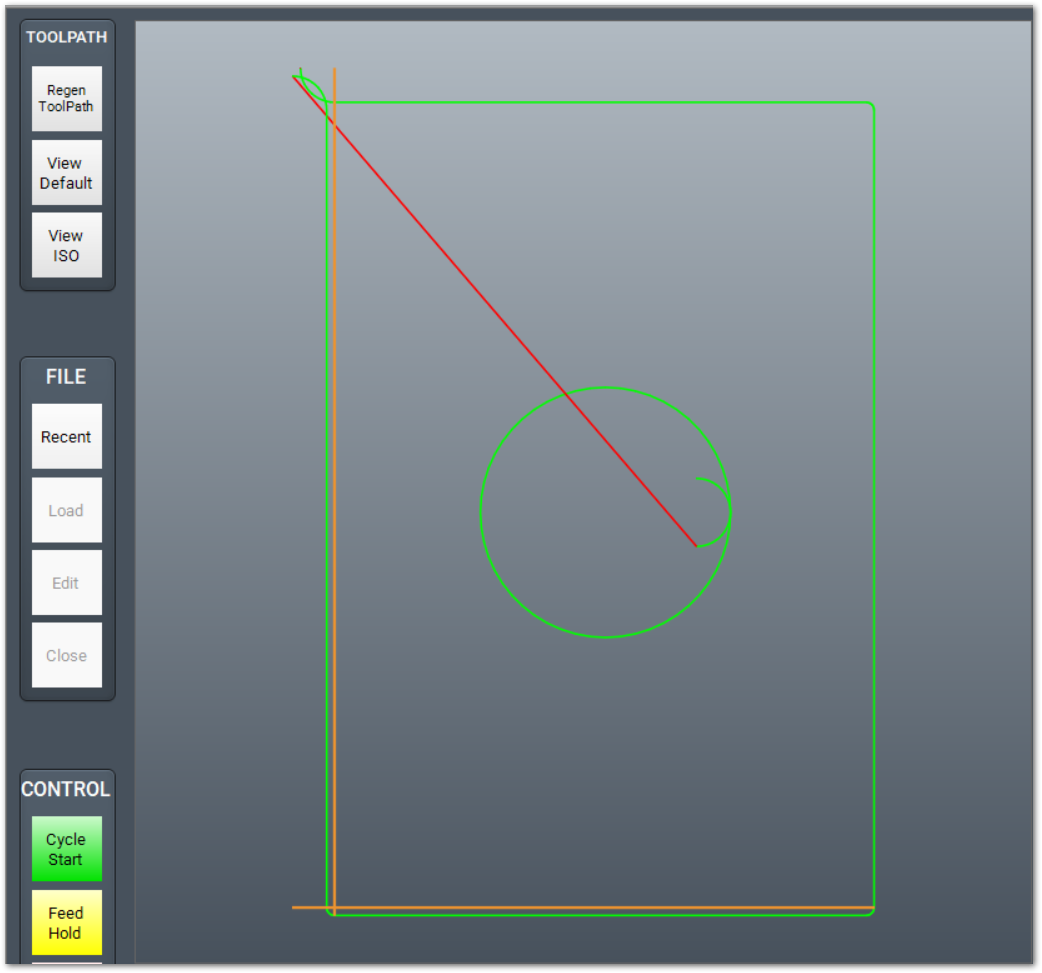
Rotate 180
|
Original
|
Rotate 180
|
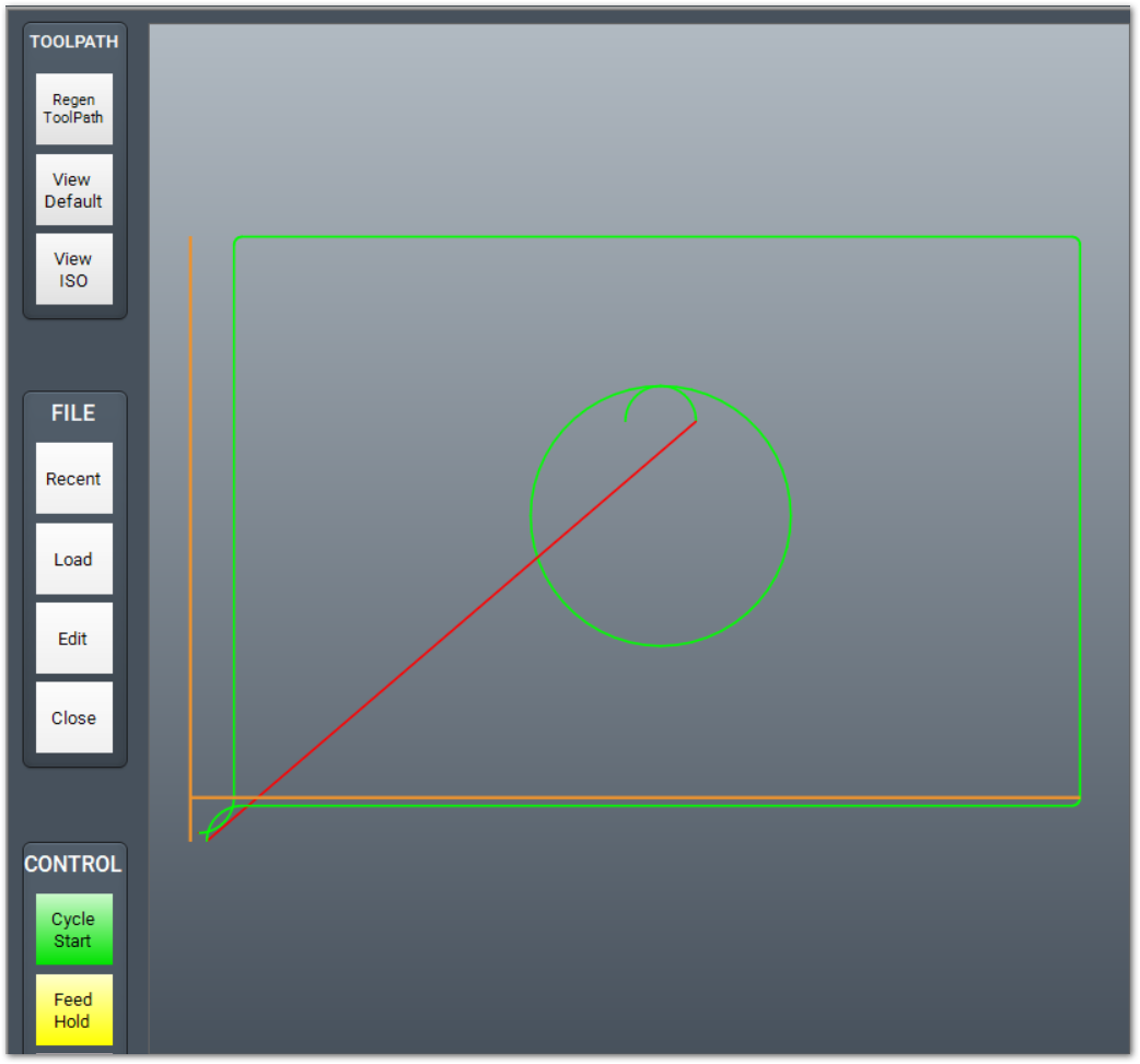
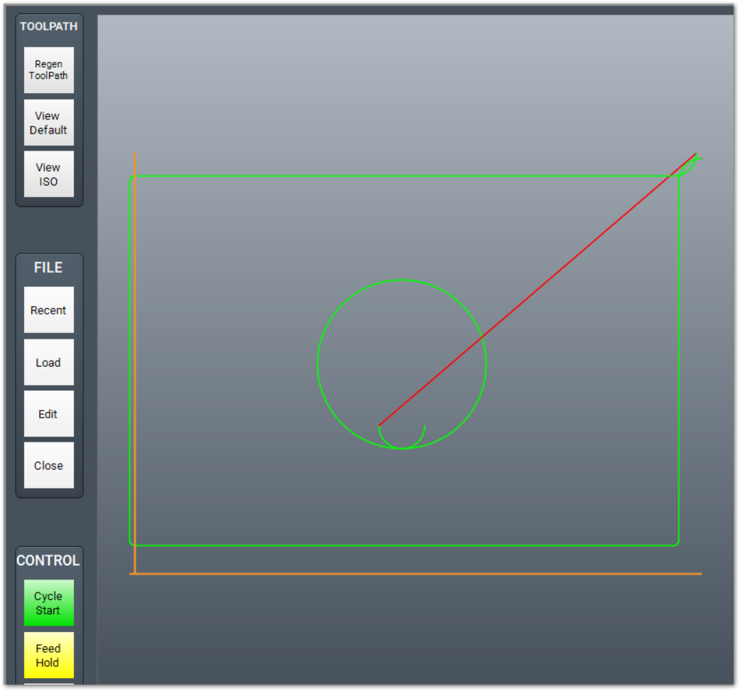
Rotate 90 CCW or CW
Use Rotate 90 CCW to turn the loaded toolpath 90 degrees counterclockwise.
- Load the source G-code file.
- Click the button that runs Transform: Rotate 90 CCW or 90 CW.
- Examine the adapted toolpath.
- Start the cycle when the toolpath is correct.
MachPro creates an adapted rotated file and loads it. Positive rotation values rotate counterclockwise. Negative rotation values rotate clockwise.
|
Original
|
Rotate 90 CCW
|
Rotate 90 CW
|
{{@2016}}