MachPro Plasma Setup Manual
{{@2007#bkmrk--1}}
MachPro 26 CNC Software Roadmap

Configure Motion Controller
Please refer to your motion controller's documentation to:
- Establish the network connection to the MachPro computer
- Connect and configure drives
- Connect and configure I/O
- Calibrate the axes
- Establish machine zero
- Configure soft limits
MachPro needs to be integrated with your motion controller. If you have an M31 use the M31 Motion Control Setup Manual If you have a compatible motion controller, then use MachPro Compatible Motion Controller Configuration Settings
Default I/O Mappings
For both input and output signals: refer to the Mapping Signals section of the MachPro motion control configuration documentation for your motion controller. See the links in the table above. Manually trigger all inputs to verify they show correctly in the software, and manually trigger all outputs from the software to make sure that the device will operate properly.
A spreadsheet is attached (upper left corner of this window) with the default I/O signal mappings. You may print it for your use during the I/O configuration.
- Wiring reference and change notes
- Update descriptions in Input and Output signals configuration to match the way you have used the system previously
- Reference for future maintenance and updates to your system
Inputs
| SignalID | SignalName | Enabled | Device/Name | Active Low | State | Description |
| 1 | Input #0 | 1 | M31/1DI.01.00 | 0 | GENERAL INPUT 0 (1DI.01.00) | |
| 2 | Input #1 | 1 | M31/1DI.01.01 | 0 | GENERAL INPUT 1 (1DI.01.01) | |
| 3 | Input #2 | 1 | M31/1DI.01.02 | 0 | GENERAL INPUT 2 (1DI.01.02) | |
| 4 | Input #3 | 1 | M31/1DI.01.03 | 0 | GENERAL INPUT 3 (1DI.01.03) | |
| 5 | Input #4 | 1 | M31/1DI.01.04 | 0 | ARC OK (1DI.01.04) | |
| 6 | Input #5 | 1 | M31/1DI.01.05 | 0 | BREAKAWAY ERROR (1DI.01.05) | |
| 7 | Input #6 | 1 | M31/1DI.01.06 | 0 | PLASMA ERROR (1DI.01.06) | |
| 8 | Input #7 | 1 | M31/1DI.01.07 | 0 | AIR PRESSURE (1DI.01.07) | |
| 65 | Motor 0 Home | 1 | M31/1DI.01.09 | 0 | X1 HOME (1DI.01.09) | |
| 66 | Motor 1 Home | 1 | M31/1DI.01.11 | 0 | Y HOME (1DI.01.11) | |
| 67 | Motor 2 Home | 1 | M31/1DI.01.12 | 0 | Z HOME (1DI.01.12) | |
| 68 | Motor 3 Home | 1 | M31/1DI.01.13 | 0 | X2 HOME (1DI.01.13) | |
| 97 | Motor 0 ++ | 1 | M31/1DI.01.08 | 0 | X LIMIT ++ (1DI.01.08) | |
| 98 | Motor 1 ++ | 1 | M31/1DI.01.10 | 0 | Y LIMIT ++ (1DI.01.10) | |
| 99 | Motor 2 ++ | 1 | M31/1DI.01.12 | 0 | Z LIMIT ++ (1DI.01.12) | |
| 129 | Motor 0 -- | 1 | M31/1DI.01.09 | 0 | X LIMIT -- (1DI.01.09) | |
| 130 | Motor 1 -- | 1 | M31/1DI.01.11 | 0 | Y LIMIT -- (1DI.01.11) | |
| 161 | Probe | 1 | M31/1DI.01.14 | 0 | PROBE (1DI.01.14) | |
| 164 | E-Stop | 1 | M31/1DI.ESTP | 0 | ESTOP (1DI.ESTP) | |
| 183 | Probe1 | 1 | M31/1DI.01.15 | 0 | PROBE 2 (1DI.01.15) | |
| 251 | Input #100 | 1 | M31/1DI.ALRM | 0 | DRIVE FAULT (1DI.ALRM) |
Outputs
| SignalID | SignalName | Enabled | Device/Name | Active Low | State | Description |
| 1050 | Output #0 | 1 | M31/1DO.01.00 | 0 | GENERAL OUTPUT 0 (1DO.01.00) | |
| 1051 | Output #1 | 1 | M31/1DO.01.01 | 0 | GENERAL OUTPUT 1 (1DO.01.01) | |
| 1052 | Output #2 | 1 | M31/1DO.01.02 | 0 | GENERAL OUTPUT 2 (1DO.01.02) | |
| 1053 | Output #3 | 1 | M31/1DO.01.03 | 0 | GENERAL OUTPUT 3 (1DO.01.03) | |
| 1054 | Output #4 | 1 | M31/1DO.01.04 | 0 | VENT (1DO.01.04) | |
| 1055 | Output #5 | 1 | M31/1DO.01.05 | 0 | LASER (1DO.01.07) | |
| 1056 | Output #6 | 1 | M31/1DO.01.06 | 0 | SCRIBE TOOL (1DO.01.06) | |
| 1057 | Output #40 | 1 | M31/1DO.01.07 | 0 | TORCH (1DO.01.05) | |
| 1142 | Spindle Fwd | 1 | M31/1DO.FE | 0 | (DRILLFORWARD) 1DO.FE | |
| 1143 | Spindle Rev | 1 | M31/1DO.RE | 0 | (DRILL REVERSE) 1DO.RE |
Languages
{{@2205}}
Probing Configuration
For MachPro prior to version 2026.5.13.1 MachPro Probing Wizard
For MachPro versions 2026.5.13.1 and after MachPro Blum Probing Routines
Modifying GoTo Positions
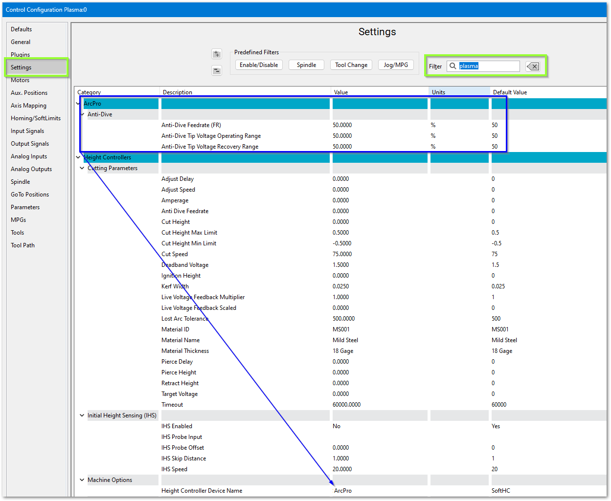
Configure MachPro Plasma
These are the minimum software settings to integrate your power unit with MachPro.
- Pull down Configure -> Control and select the Settings tab
- In the upper right corner of the window, enter plasma as the filter term

ArcPro height controller
Verify these settings
Soft Height Control

Roller Head
If you are using a roller head, change the Plasma Style to Roller Head and update these settings to match your system

Initial Height Sensing (IHS)
This is usually implemented with an ohmic contact, torque/motor-stall sensing, or a floating head switch. These are the options for configuring IHS.

Laser settings

{{@2016}}