MachPro Plasma Setup Manual
{{@2007#bkmrk--1}}
MachPro 26 CNC Software Roadmap

Configure Motion Controller
Please refer to your motion controller's documentation to:
- Establish the network connection to the MachPro computer
- Connect and configure drives
- Connect and configure I/O
- Calibrate the axes
- Establish machine zero
- Configure soft limits
MachPro needs to be integrated with your motion controller. If you have an M31 use the M31 Motion Control Setup Manual If you have a compatible motion controller, then use MachPro Compatible Motion Controller Configuration Settings
Languages
{{@2205}}
Configure the Dedicated Network Interface
The motion controller connects to the control computer through an IP Ethernet connection, and we recommend you use static IP addresses for both the computer and the motion controller.
Follow the Microsoft guide below to manually set a static IP address on the computer: Microsoft Instructions: Manually Configure IPv4 Settings Scroll to the bottom and expand the section titled “To specify IPv4 settings manually.”
Then perform the following steps to use the MachLabs default settings:
SetIP addressto:192.168.208.10SetSubnet maskto:255.255.255.0Save the settings and close the window.Connect to thededicated network porton the control computer.
Axes Configuration
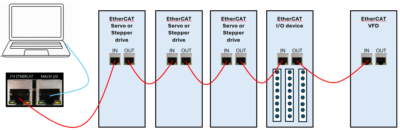
EtherCAT Recommendations
Put servo & stepper drives firstin the EtherCAT chain (closest to the controller).Put I/O devices and safety relays in the middle.Put VFDs last(at the end of the chain). VFDs make electrical noise — keeping them last lowers interference.Use shielded network cablefor all EtherCAT devices.Cable length:keep each cable between1 foot and 100 meters(about0.3 m – 100 m).Good cable management:keep cables neat, do not bend them sharply, and separate network cables from high-power lines when possible.
Enabling Axes in MachPro
Enabling Axes
After the drives are configured with the motion controller, open up MachPro, and enable the axes as follows:
Enable all the motors that are to be controlled by setting the respective boxes in the right pane to checks. In the example below, motors 0, 1, 2, and 6 are enabled.If a motor moves the wrong direction, it can be reversed in the MachPro. Check theReverse?box if the motor direction needs to be reversed. The motor will now move the opposite direction than it did before. If the homing direction was already set, it will need to be reversed as well. (see the homing section ). NOTE: If you are needing to reverse direction on an axis with a slave motor, you may need to change the direction for both the master and slave axis.Press [Apply] to save any changes.
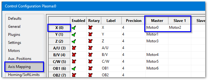
Next, select theAxis Mappingtab as pictured below. Associate the enabled motors to the applicable axis. In this example, Motor0 is the X master, Motor1 is the Y master, and Motor2 is not mapped to an axis. No slave axes are configured on this system.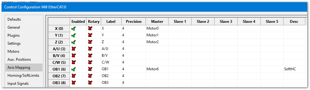
If you have an axis with two motors - such as a gantry - one motor will be the master and the second will be the slave. In the slave column, select the motor that will be running in slave mode. In this example X axis has Motor0 as the master and Motor2 as the slave.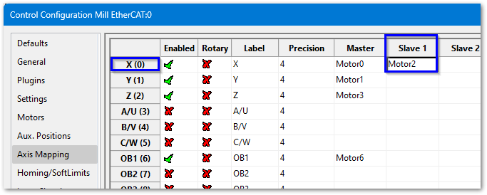
Press [Apply] and [OK] to save and close.Carefully test jogging. If you have a gantry with two motors, you may need to reverse one motor for correct motion. See step 2 above.


The system should now be able to jog, however,....
WARNING The machine can be crashed very easily at this point. The axes need to be calibrated and the limits set up now.
Axis Calibration
Before calibrating the axes, set the backlash units to 0 for each axis. See Backlash Repair and Compensation for details.
Go to Configure-> Plugins -> Machine Calibration.
Select the type of configuration you would like to perform from the window:
Manual - Calculate the axes by comparing distance traveled vs. distance commanded. SeeManual Calibrationbelow for instructions.Automatic - Calibrate axes using the specifications of your system. Continue for instructions.
Automatic Units Calibration
Automatic calibration requires you to provide all of the details of your motor and axis hardware. If you are unable to find this information, proceed to the Manual Calibration section.
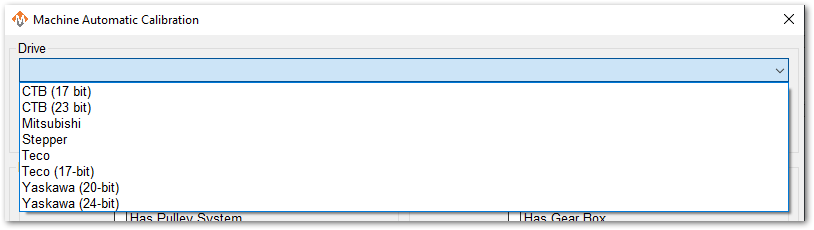
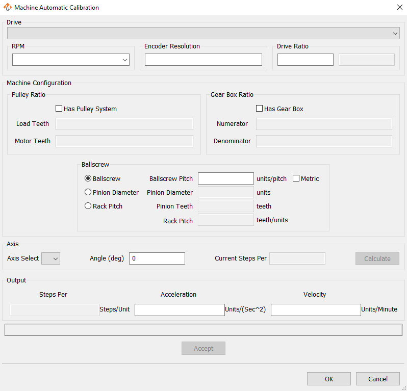
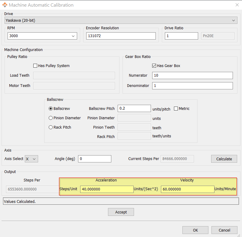
Select the Drive that most closely matches yours. If there is not an exact match, select based on the number of encoder resolution bits.Select the max motor RPMEnter the Encoder Resolution. To verify the actual encoder resolution of your drive, please use the steps above inChecking Resolution.Enter 1 for the drive ratio.If this axis uses a pulley, select that box and enter the number of teeth from the load side and the motor side.If there is a gearbox, select that box and enter the ratio.This axis will have either a ballscrew or rack and pinion system. Select the type it has and complete the open fields.Select the axis to calibrate.Leave Angle at 0 degreesPress the [Calculate] button.Evaluate the current steps value against the proposed values. You may change values and re-calculate.When you are ready to Accept the new steps per value, enter in the maximum Acceleration and Velocity values that you want for this axis.
Repeat for each axis.
Press [OK] and restart MachPro to save the calibration settings.
This is an example of a simple X axis that has been calculated and is ready to be accepted. You may need to change the Acceleration and Velocity values to be appropriate for your machine.
Verify that each axis is moving the distance that you command.
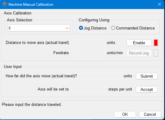
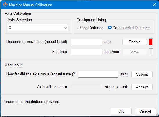
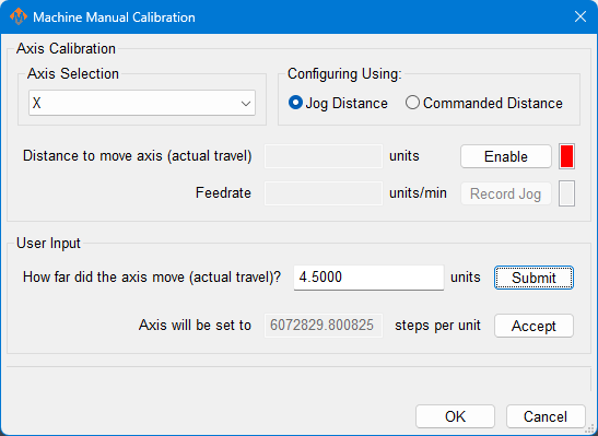
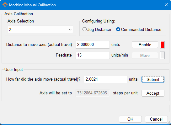
Manual Calibration
This tool will enable you to calibrate your axes based on measuring actual distances moved and updating the MachPro parameters. Use the longest distance that you can accurately measure to calibrate each axis.
You will be commanding motion on each axis. Carefully jog each axis to the middle of travel before starting calibration.
Select the axis to calibrate.Select either Jog Distance or Commanded Distance. Jogging allows you to directly control the speed and distance the axis moves.
|
|
|---|---|
|
|
|
|
|
|
Axis calibration is a core function of a CNC control. Ensure that it now meets your accuracy requirements before moving on in the configuration. All of the following configuration steps depend on calibration, and if you later change the calibration, you will need to reconfigure many of the items below.
Configure Velocity and Acceleration
If you want to adjust your velocity, select Configure on the top menu bar, then Control . Select the Motors tab as shown below.

In the right pane, click on the motor you want to set up.
Click the word to highlight and select the axis. The checkbox is for enabling/disabling the motor
The selected motor’s parameters will be loaded and the velocity or acceleration settings can be adjusted.
The max velocity is limited by several factors, including the motor. If you want an axis rapid speed to be limited or lowered, adjust the velocity for that motor to the max speed you want the rapid to be. The rigidity of the machine hardware will limit practical maximum velocity of an axis. The cut quality and accuracy will degrade as it reaches that point.For stepper motors, max acceleration is typically 15-20 if in standard units. For servo motors, start with value of 30-40. This parameter also sets the deceleration rate, which interacts with a regeneration resistor - if one is installed on this axis.
Press [ Apply ] before clicking on another motor or closing out the MachPro Configuration window. NOTE: If you change the counts per unit, the velocity and acceleration values will adjust accordingly. If you do not want them to change, type in the current values shown. Verify by clicking another motor and then coming back to the adjusted motor.
WARNING No limits have been set up. DEATH, INJURY or serious PROPERTY DAMAGE can occur if the system is not operated carefully. Limits and homing setup will be completed in section 3
Backlash Repair and Compensation
Backlash is caused by the gaps between moving parts such as gears and ballscrews. It is the amount of movement one component can make in one direction without causing motion in the next connected part. Most mechanical systems have some backlash - even when new. If the mechanics are too tight, binding and excessive wear will result. As the gears and ballscrews wear, the backlash will increase, and accuracy will decrease. Ongoing testing and maintenance of your mechanical system is required to minimize backlash. To calculate the backlash of an axis use How To Test For Backlash
All of the axes are now calibrated, but MachPro does not know where the limits of travel are on each axis. That will be configured next. Until that setup is completed, be very careful if you are moving axes
I/O Signal Mapping
Short example
Inputs #0 through #8 are enabledInputs #0 through #5 are mapped to the M31 motion controller, and unique inputs on the M31All of the inputs shown are active high except for Inputs #3 and #4The state column shows that Inputs #3 and #4 are also active nowDescriptions have been added to Inputs #0 through #8. These are the descriptions that the operators and designers will use.
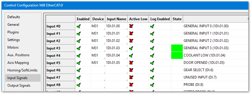
If you have limited inputs on your motion controller, there are two ways that MachPro can be configured to conserve those inputs:
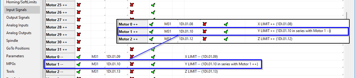
You can wire the axis limits for the positive and negative sides in series, and map the two software signals to the same device and input name. If either limit trips, MachPro will stop the motion to protect your system.
You can wire one switch to function as both a limit and a home switch. When the system is homing, it will treat the device mapped to the software home signal as a homing switch. Once the system has been homed, it will stop looking for a home signal, and any input from that switch will be treated as a limit switch.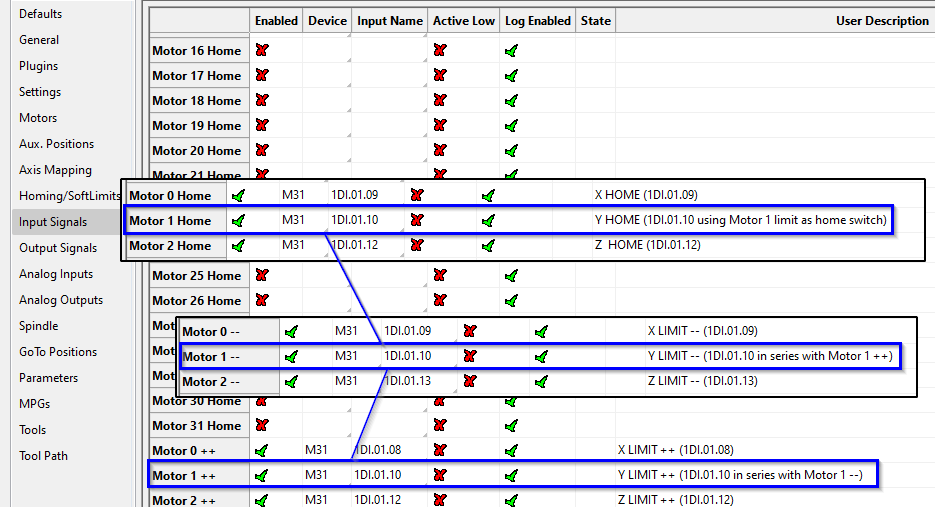

There are caveats to this approach.
You will need to ensure that when that axis homes, it moves the correct direction. This is configured inHoming Setup.When the machine trips either the positive or negative limit, it will see both signals becoming active, and you will not be able to jog the machine off the limit.Go to theService tab, and click theLimit Overridebutton in the upper left cornerJog that axis off the limitTurn off theLimit Override
Using Outputs
Outputs 0-5 can be controlled with M-Codes. One M-Code turns an output on, and the other M-Code turns the output off. Use the table below for a reference.
|
|
|
|
|
|
|
| |
|
|
|
|
| |
|
|
|
|
| |
|
| |
|
| |
|
| |
|
| |
|
| |
|
|
Homing Setup
Danger:If limit switches are wrong or an axis moves the wrong way, the machine cancrash.Do this first:Keep your hand on theEmergency Stopbutton thefirst timeyou run homing.Open the settings:From the menu bar clickConfigure → Control. Then click theHoming/SoftLimitstab.

Home Dir:Pick the direction the axis will move to find home —positiveornegative.Home Order:Set the order of homing using numbers (1 = first, 2 = second, etc.).Tip:Zis often set to1so it moves up first and stays out of the way.
Home Speed%:Set how fast the axis homes by choosing a percent.20%is the usual maximum for best results.Slower speeds help stop over-travel.You canjog(move) the axis quickly close to the home position before homing to save time.
Home In Place:Set this based on your motion controller config:If you usehome switcheswired through your motion controller → make sureHome In Placeshows ared X.If you useabsolute encodersin your motion controller → make sureHome In Placeshows agreen ✓.
Save:PressOKto save your changes.Switchto theService tabTest:Home each axis one by one to check the settings. Then pressHome Allto verify everything works.
Soft Limits Setup
Use the Control->Configuration menu and open the Homing/SoftLimits tab. When the machine is homed correctly and soft limits are set, the machine will not hit a physical limit switch. If at any time a command is made for the machine to move outside of the soft limits (while they are enabled), an error will appear in the status line and motion will stop. To set up the soft limits, follow the procedure outlined below.
Home the machine.Toggle theViewing Partbutton under the DRO to select theMachine Coordinatesview. The button and DRO’s will be orange while viewing the machine coordinates.Jog the machine to the maximum safe distance from the homing switches.Note: Make sure to stay inside the physical limit switches. If the machine is jogged outside of the limit switches, it completely defeats the purpose of soft limits.
Record the machine coordinates at the end of the travel for each axis.Jog the machine to the maximum safe distance beyond the homing switches, and record the machine coordinates for each axis.Open the menu bar and clickConfigure->Controland select theHoming/SoftLimitstabEnable soft limits on each desired axis by setting theSoft Enablecolumn to a green check mark, and enter in the recorded values.For each axis, enter the largest, most positive value in the Soft Max field, and the smallest, most negative value in the Soft Min field.
Press [OK] to save changes. Test the soft limits by jogging the axes to maximum amounts in all directions.

Note: When loading a G-code file, the tool path display will show the soft limits as dashed lines. If any part of the tool path renders outside the soft limits, check your file.
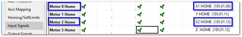
Gantry Homing Setup
There are 2 configuration options:
1. Homing with the home switch only on the Master
|
|
|
|


2. Homing with both Master and Slave having their own home sensors
|
|
|
|
Probing Configuration
{{@2015}}
Modifying GoTo Positions
{{@2045}}
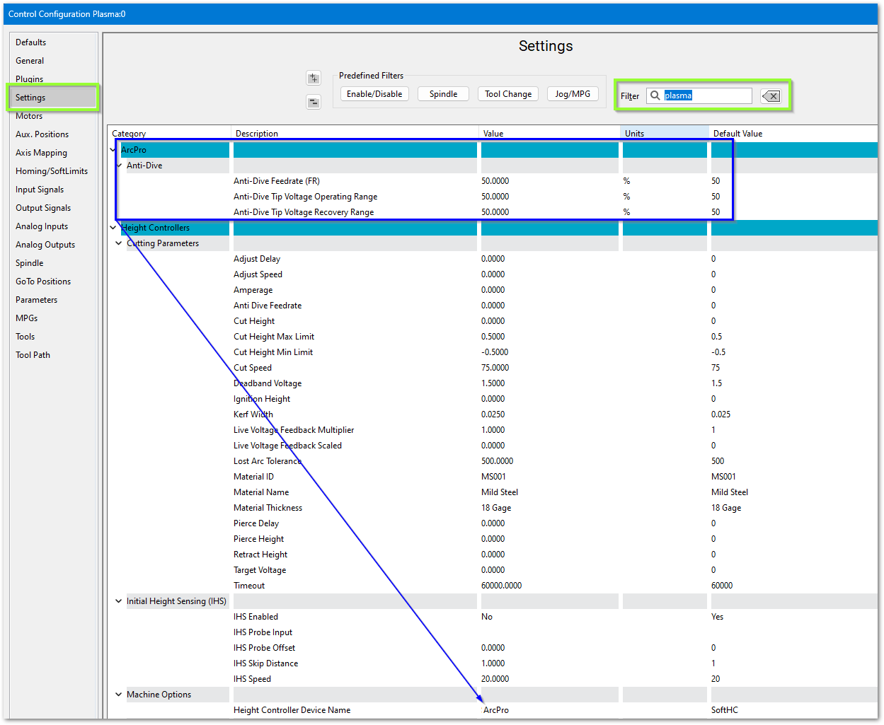
Configure MachPro Plasma
These are the minimum software settings to integrate your power unit with MachPro.
- Pull down Configure -> Control and select the Settings tab
- In the upper right corner of the window, enter plasma as the filter term

ArcPro height controller
Verify these settings
Soft Height Control

Roller Head
If you are using a roller head, change the Plasma Style to Roller Head and update these settings to match your system

Initial Height Sensing (IHS)
This is usually implemented with an ohmic contact, torque/motor-stall sensing, or a floating head switch. These are the options for configuring IHS.

Laser settings

{{@2016}}