
MachPro Plasma Operating Manual
{{@2007#bkmrk--1}}
Introduction
Overview
This manual gives an overview for the basic operation of the MachPro Plasma control. The screens are shown below, followed by a brief summary of the features of each screen. The numbers shown in the screenshot refers to a brief description below the image.
Control Startup
To open the control software, double-click on the profile icon on the desktop.

Languages
{{@2205}}
Control Screens Overview
G-code Tab

- Toolpath
- Regen Toolpath: refresh the displayed toolpath
- View Top: top view of the part
- View ISO: side view of the part
-
The controls to manipulate the toolpath screen are as follows:
-
- Zoom – Right click with the mouse and move mouse up/down or using the scroll wheel on the mouse
- Rotate – Left click with the mouse and rotate the part by moving the mouse
- Pan – Press and hold [Ctrl] on the keyboard and left click with the mouse, then pan by moving the mouse (one-hand control option is to use left and right mouse click and move the mouse. No [Ctrl] press needed)
-
- File
- Recent: load a recently loaded G-code program
- Load: load a G-code program from the computer
- Edit: edit the G-code program currently loaded into the control
- Close: close the G-code program that is currently loaded into the control
- Advanced
- Single Block: when active, the control will go line by line through the G-code program when the operator presses [Cycle Start]
- Block Delete: when active, the control will skip the lines in the G-code program indicated by their block level
- Part Counter: displays the number of parts that the machine has produced
- M1 OPT Stop: when active, the control will stop at any M1 command in the G-code program and wait for the operator to press [Cycle Start]
- Dry Run: when active, the control will ignore all mist or flood commands
- M-S-T Lock: when active, the control will ignore all M-codes, jet commands, and tool commands
- File Resume: allows the operator to select a line of G-code to start the program from and makes the control ready to run from that location
- Collapse: minimizes the advanced section to only show M1 OPT Stop and File Resume
- Status
- Status: displays the most recent message
- State: displays the current control state
- Cycle Time: displays how long the G-code program has been running
- Date: displays the current date and time of the control
- Axis Digital Readouts
- For each axis on the control, there is the following:
- A DRO displaying the current position
- A DRO displaying the distance left to travel
- A gauge displaying the current load on the axis
- Indication that the axis has not been homed if the axis letter is flashing red and yellow
- MDI: opens or closes a window for G-code commands
- Viewing Part: toggles the axis position DROs between machine coordinates and the current fixture coordinates
- The buttons across the bottom of the DRO section can be customized by right-clicking on them. See Dashboard configuration and configuring GoTo positions for detailed options. The transform functions can be particularly useful on shape cutting systems.
- For each axis on the control, there is the following:
- Feedrate Display
- F: displays the current commanded feedrate
- Feed OV: displays the current feedrate override percentage (0-300%)
- Rapid OV: displays the current rapid override percentage (0-100%)
- Tool Display
- T: displays the current selected tool number
- Next Tool: displays the next tool to be used by the G-code program
- Torch Height Control
- Live Voltage: Can be scaled according to the divider specification of the power unit
- Target Voltage: adjustable with - and + buttons, normally set using the Tech Tables
- Cut Height: adjustable with - and + buttons, normally set using the Tech Tables
- Pierce Height: adjustable with - and + buttons, normally set using the Tech Tables
- Pierce Delay: adjustable with - and + buttons, normally set using the Tech Tables
- Job Status
- THC State
- Material: selected with the Tech Tables button
- Counters: can be reset with the Reset Counters button
- Control Buttons
- Move to Path, Move to Start, Cut Recovery (See the Cut Recovery documentation)
- Tech Tables: The tables for the materials and appropriate plasma settings for each material
- Auto Voltage Control: Maintains a set voltage
- Smart Target Voltage: Maintains a voltage determined during the first portion of the cut
- Initial Height Sensing (IHS): Detects the Z height of the part
- Reset Counters
| Method | What it controls | When it happens | Reference used | Plain-English distinction |
|---|---|---|---|---|
| Initial Height Sensing, IHS | Finds the material surface / Z reference | Before the cut starts | Physical plate position | “Where is the top of the material?” |
| Auto Voltage Control, AVC | Maintains torch height during cutting | During the cut | A fixed target voltage set by user/table | “Keep the arc voltage at this set value.” |
| Smart Target Voltage | Maintains torch height during cutting | During the cut, after learning | Voltage measured during the first stable portion of the cut | “Learn the right voltage from this cut, then hold that value.” |
In plasma cutting, arc voltage is used as a proxy for torch height. Generally, a higher arc voltage means the torch is farther from the plate, and a lower voltage means the torch is closer.
A typical sequence is:
-
- IHS touches/probes/senses the plate to find the correct Z reference.
- The machine moves to pierce height and fires the torch.
- After the arc stabilizes, torch height control begins.
- The system then uses either:
- AVC, using a predefined voltage target, or
- Smart Target Voltage, using a voltage learned from the early part of the cut.
So the key difference is:
IHS finds the starting physical height. AVC holds a manually/table-defined voltage. Smart Target Voltage automatically determines the voltage target from the actual cut and then maintains it.
11. Plasma Status Indicators: these turn green when they are active
-
- IHS
- Torch
- Arc OK
- THC
- UP
- DN
- FR Lock
- VT Lock
12. Side Dashboard
-
- Jogging
-
-
- Torch On
- Scribe Tool
- Laser Pointer
- There is an extensive collection of widgets that can be used on the dashboards in MachPro. This doc: MachPro Widgets, Dashboard, Commands, and Function Buttons provides the details for selecting, configuring and using the available widgets.
-
14. Control
Control- Cycle Start - Starts the gcode from from the beginning of the part
- Feed Hold - Pauses the gcode program and keeps the spindle running
- Cycle Stop - Stops the gcode program from running
- Reset - Resets the alarm and also enables the machine
- Disable - Disables the control for software configuration changes
Tools Tab

- Edit
- Edit Offsets - No offset changes can be made unless this value is yellow. It also displays or hides the part zero buttons just left of the DROs.

- Edit Offsets - No offset changes can be made unless this value is yellow. It also displays or hides the part zero buttons just left of the DROs.
- Tools
- Tool Table - View and edit tool table.
- Pockets
- Register Tools - Register and save tools
- Setters
- Tool Setters - Select this to add or remove a tool setter. See MachPro Tool Setters and Offsets
- Park Tool - Park the currently loaded tool and leave the spindle empty
- Jump to Tool Number
- 1,2,3,4 etc. - Tool number (Tool change). Just press the button and the tool will change.

Fixtures Tab
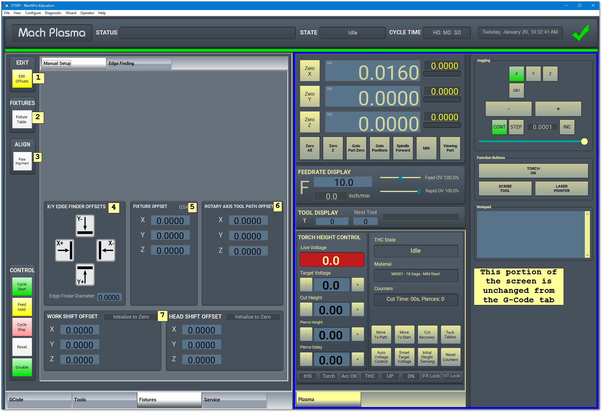
- Edit
- Edit Offsets: edit the active fixture offsets
- Fixtures
- Fixture Table: view and edit the fixture table for all fixtures
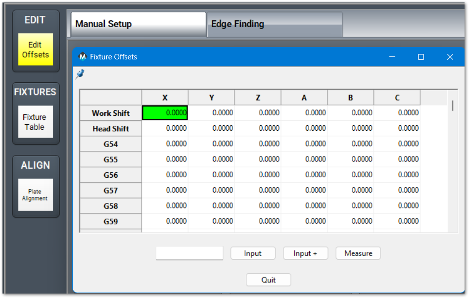
- Fixture Table: view and edit the fixture table for all fixtures
- Plate Alignment
- X/Y Edge Finder Offsets
-
- Jog the X axis until the probe touches the edge of the part.
- Click the X+ button in the X/Y Edge Finder Offsets.
- Click Yes to modify X fixture offset


-
- Fixture Offset will display the current G____ offset, and the value of that offset. Here the G54 X offset is being changed from 3.2300 to 3.231. This value is in machine coordinates.
-
Double click on the value you want to modify

Type in the new value and press Enter on the keyboard 
-
- Axis offsets for the rotary axes
- Work and Head Shift Offsets. Details on work and head offsets
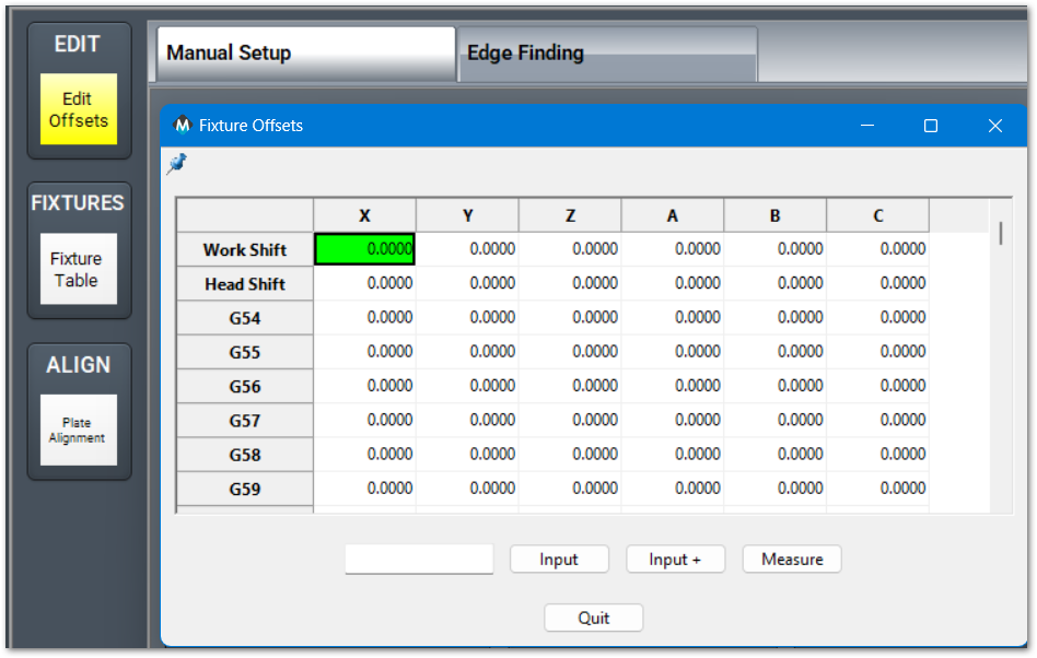


Service Tab
Maintenance Tab

- Limits
- Soft Limits: toggles software limits on or off
- Limit Override: toggles to allow for the machine to move off a limit switch
- PLC
- Reset Pocket: only used for tool changers
- PLC Sequence
- Commands (CMDS)
- This is a tool to run special commands. Contact support for assistance.

- This is a tool to run special commands. Contact support for assistance.
- Settings
- Interface Config: opens the MachPro operator panels configuration window
- Motion Controller: opens the configuration for the active motion controller
- Screen Config: opens the configuration to change the colors and password protect aspects of the screen
- Industrial Theme: applies standard colors to screen objects
- Menu Config: opens settings for top menu bar
- Compile Scripts: refreshes programming scripts
- Support
- Remote Support: starts a TeamViewer session
- Online Support: opens the online support page
- Online Manuals: opens the MachGroup bookstack site
- History: view the operator message history
- User
- Logout: logs out of the Windows session
- Power: turns off the computer
- Homing
- Home X: sends X axis to do its homing routine
- Home Y: sends Y axis to do its homing routine
- Home Z: sends Z axis to do its homing routine
- Home All: all axes do their homing routine in their configured order


Dashboard Tab
The dashboard is used add information and control widgets. Dashboard configuration
Machine I/O Tab
This tab is used for diagnostics and shows all enabled machine signals.
Homing
To home the machine, or set the machine zero for this session, begin by pressing the [Reset] button. Then navigate to the [Service/Maintenance] tab and press [Home All]. There is an optional parameter to prompt the user to home the machine on startup.
Programmed Movement
MDI
To command a movement using the MDI feature, press the [MDI] button.


G-code
The primary method of commanding motion is using G-code files. G-code files can be hand written, generated by a wizard, or generated from CAD files using a CAM program. MachPro G-Code and M-Code Reference
{{@2016}}