MachPro Lathe Operating Manual
{{@2007#bkmrk--1}}
Introduction
This manual gives the process for basic operation of a using the MachPro Lathe control. The screen is shown below, followed by a brief summary of the different features of the screen. The number shown in the screenshot refers to a brief description below the image.
To open the control software double-click on the profile icon on the desktop.

Control Screen Overview:
GCode Page
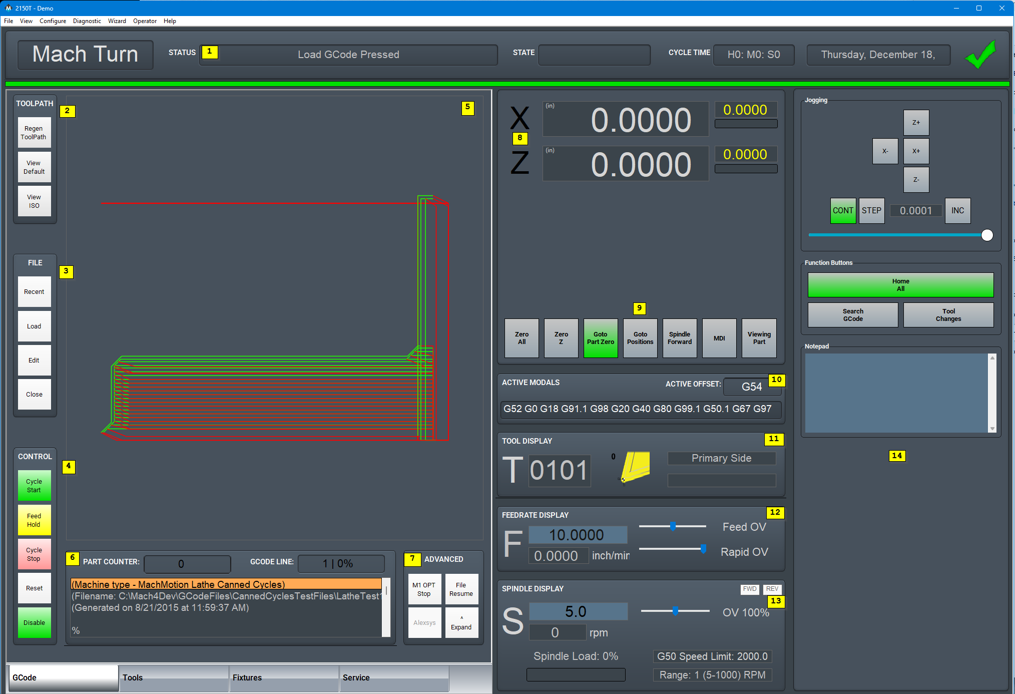
- Status
- Status - Displays any current messages (Home All Pressed, Cycle Start Pressed, etc.)
- State - Displays the current state of the machine (Run, Feedhold, etc)
- Cycle Time - Displays how long the GCode has been running
- Date - Date and time of the timezone of the control
- Tool Path
- Regen ToolPath - Refresh the toolpath of the GCode
- View Top - Top view of the part
- View ISO - Side view of the part
- File
- Recent - Load a recently loaded GCode program
- Load - Load a program from the computer or flash drive
- Edit - Edit the code that is loaded into the software
- Close - Close the GCode that is currently loaded in the software
- Control
- Cycle Start - Starts the gcode from from the beginning of the part
- Feed Hold - Pauses the gcode program and keeps the spindle running
- Cycle Stop - Stops the gcode program from running
- Reset - Resets the alarm and also enables the machine
- Disable - Disables the control for software configuration changes
- Tool Path Display
- Show the X and Y path that the machine will follow when running the GCode program
- GCode Display
- Part Counter
- GCode Line
- GCode Display
- Advanced - Expand or Collapse
- Single Block - If active the software will go line by line through the GCode when you press the cycle start button
- Block Delete - Deletes the block of GCode that is selected
- Part Counter - Displays the number of parts that the machine has produced
- M1 OPT Stop - If active the software will stop at any M1 commands in the GCode program and waits for cycle start
- Alexsys - Opens up the conversational assistant Alexsys in another window (if installed)
- Dry Run - If active the software will ignore all mist or flood commands
- M-S-T Lock - If active the software will ignore all Macro codes, Spindle codes and Tool commands
- {{@2013}}
- Collapse v - If selected this will minimize the Advanced buttons
- Position Display
- Axis Positions - Large DROs
- Distance To Go - Yellow DROs
- Configurable Gauge - Axis Load or Velocity
- Position Display Dashboard
- MDI - Opens up a window that allows for GCode commands
- Viewing Part - Shows the part coordinates or machine coordinates of the machine
- 5 Configurable Function Buttons
- Active Modals
- Active Offset - Shows the current active fixture offset (G54, G55, etc)
- Tool Display
- T - The current – the first two digits refer to the tool and the second two refer to the offset
- Picture – shows the current tip direction of the tool
- Tool Post – shows which tool post the tool is connected to – Primary, Secondary or not defined
- Description of the current tool
- Feedrate Display
- F - The current feedrate commanded
- Feed OV - The current Feedrate Override utilizing the Feedrate Override knob on the operating panel (0-200%)
- Rapid OV - The current Rapid Override utilizing the Rapid Override knob on the operating panel (0-200%)
- Spindle Display
- S - The current spindle speed
- Rpm - The current spindle speed feedback
- FWD - Turns on if the spindle is moving Forward
- REV - Turns on if the spindle is moving in Reverse
- Spindle OV - The current spindle override (0-200%)
- Spindle Load - The current spindle load utilizing the spindle speed feedback
- Range - Displays the current spindle range (spindle pulley)
- G50 Speed Limit - Displays the current G50 limit and changes to yellow when a limit is active
- Dashboard
- Configurable Dashboard
- Add Widgets
Tools Page
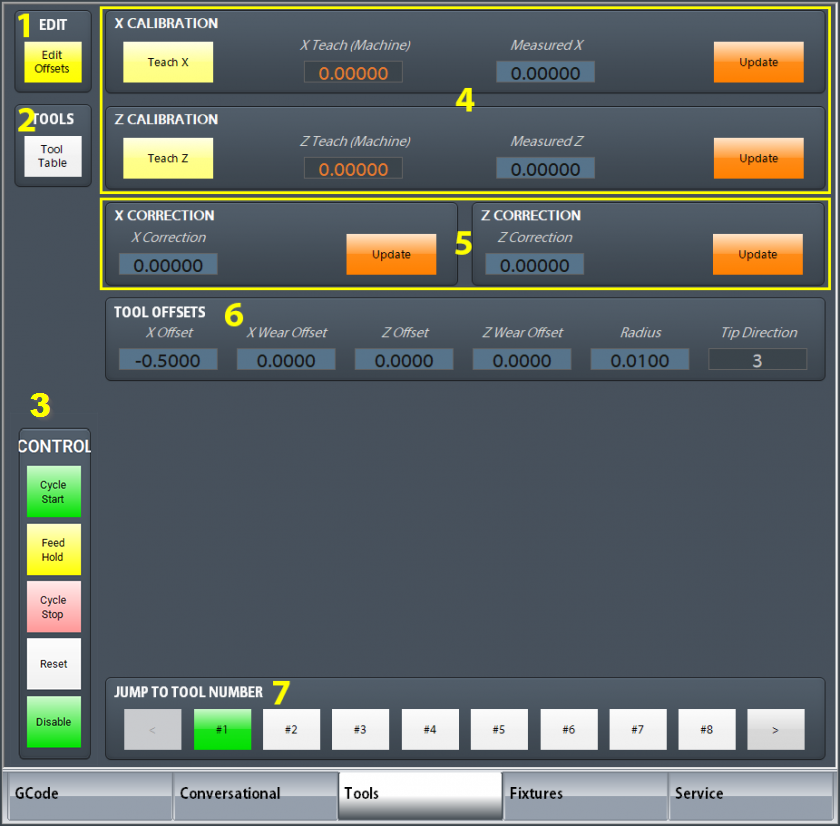
- Edit
- Edit Offsets - No offset changes can be made unless this button is yellow. It also displays the zero buttons near the DROs to the right.
- Tools
- Tool Table - View and edit tool table
- Control
- {{@1024#bkmrk-Control-Buttons}}
- X and Z Calibration
- Teach - Touch tool off on part and press teach
- Measured DRO - Enter Diameter / Position of the part where the Teach was pressed
- Update - Calculate the new value for the tool offset and store it to the tool table
- X and Z Correction
- Correction DRO - Enter the amount you want to adjust the tool offset
- Update - Calculate the new value for the tool offset and store it to the tool table
- Tool Offsets
- Displays all the values for the current tool
- Update - Calculate the new value for the tool offset and store it to the tool table
- Jump to Tool Number or Tool Pocket
- 1,2,3,4 etc. - Tool number (Tool change). Just press the button and the tool will change.
Fixtures Page
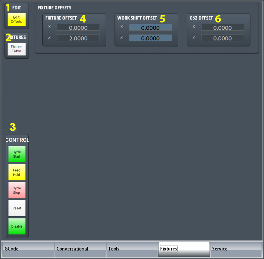
- Edit
- Edit Offsets - View and edit fixture offsets
- Fixtures
- Fixtures Table - View and edit fixture table (G54, G55, G56, etc.)
- Control
- {{@1024#bkmrk-Control-Buttons}}
- Current Fixture Offsets
- Current Work Shift Offsets
- Current G52 Offsets
Service Page
Maintenance

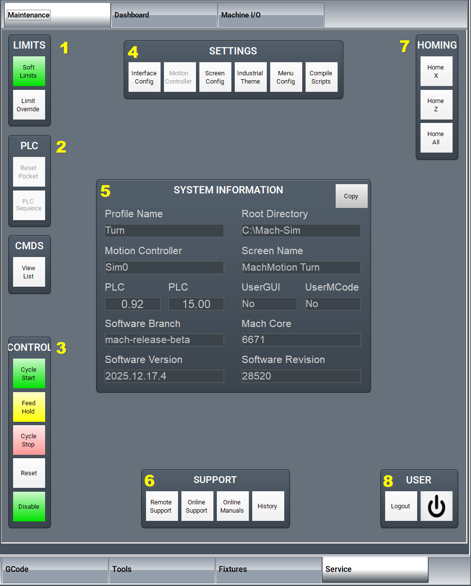
- Limits
- Soft Limits - Toggles software limits on or off
- Limit Override - Toggles to allow for the machine to move off a limit switch
- PLC
- Reset Pocket - Only used for tool changers.
- PLC Sequence -
- Enable
- Disable - Toggles if the machine is enabled or disabled
- Settings
- Interface Config - Opens the
pluginUserwithInterfaceMachMotionconfigurationConfigurationscreen - Motion Controller - Opens the plugin for the Motion Controller
- Screen Config - Edit the screen layout
- Industrial Theme - Applys Industrial Theme
- Toggle Menu - Turns the top menu on or off
- Compile Scripts - Refreshes (recompiles) programming scripts
- Interface Config - Opens the
- System Information
- Support
- Remote Support - Starts a
remote supportTeamViewer sessionwith MachMotion Technical Support - Online Support - Opens up the
onlinewebMachMotionpageSupportwithLibrarythe support options UpdatesOnline Manuals -ChecksOpensfortheupdatesMachGroupfordocumentationMachMotion Softwaresite- History - Views status history and alarms
- Remote Support - Starts a
- Homing
- Home X - Homes the X axis
- Home Z - Homes the Z axis
- Home All - Homes all axes
- User
- Logout - Logs out of the Windows username
- Power - Turns off the computer
Dashboard

The Dashboard is used to make the control just the way you want it! For more information, see this link: Configure Dashboards .
Machine I/O

This page is used for diagnostics and shows all your machine IO.
Homing
To home the Machine, begin by click the [Reset] button and then the [Service] tab and click on [Home All].
Programmed Movement
MDI
To command a movement using the MDI feature, press the [MDI] button.
Enter the desired G-Code command into the field and press [Cycle Start] to execute the command(s). The up/down arrow buttons will scroll through the history of cycled commands. Click the Red [X] to close the MDI window.

Example MDI Command
G-Code
The primary method of commanding motion is using G-Code files. G-Code files can be hand written, generated by a wizard, or generated from CAD files using a CAM program.
Tool Path Screen
Below are the controls to manipulate the tool path screen:
- Zoom – Right click with the mouse and move mouse up/down or using the scroll wheel on the mouse
- Rotate – Left click with the mouse and rotate the part by moving the mouse
- Pan – Press and hold [Ctrl] on the keyboard and left click with the mouse, then pan by moving the mouse (one-hand control option is to use left and right mouse click and move the mouse. No [Ctrl] press needed)
Tools and Tool Offsets
See the Offset tab above.
Spindle Control
G-Code Spindle Control
The spindle is controlled through G-Code using the M-Codes M3 (Clockwise), M4 (Counterclockwise), and M5 (Off). To control the spindle speed in RPMs an S word is added.
For example, M3 S2000 would turn the spindle on in the clockwise direction at 2000 RPM.
Manual Spindle Control
To control the spindle separately from G-Code use the spindleSpindle controlForward on/ Spindle Stop button below the operatingDRO.
|
|
|
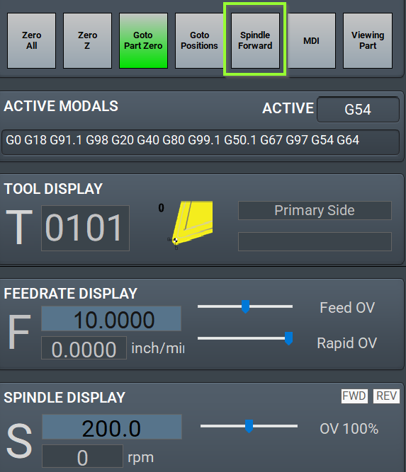
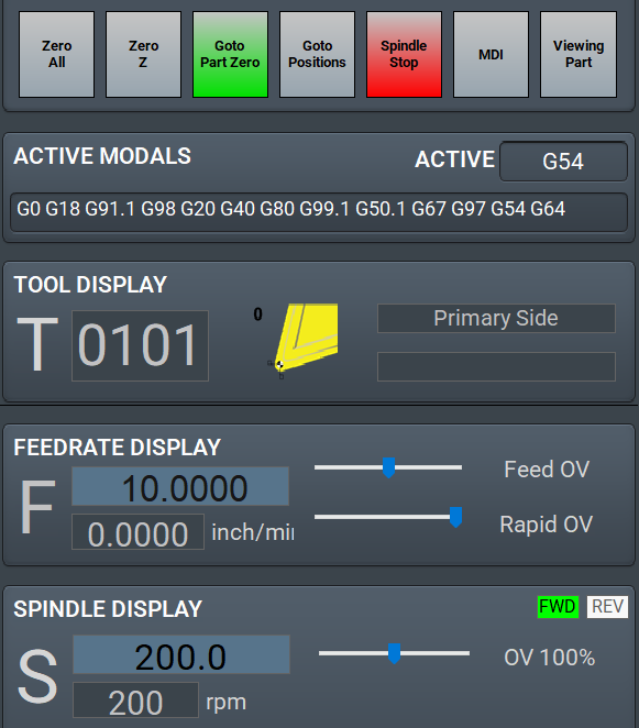
Spindle Display
The current spindle settings are shown in the main Spindle Display.

- S – Commanded Speed
- Spindle OV – Spindle Override Percentage
- Spindle Load – % of the load of the spindle
- G50 Speed Limit - Displays the current G50 limit and changes to yellow when a limit is active
- Range – Current Pulley Selected
Spindle Warm Up
MachPro has the ability to setup a Spindle Warm Up procedure for machines.{{@2023}}
To be able to configure this go to Control-> Settings tab and search for Spindle Warm Up.
Below is an example screen for the Spindle Warm Up settings.

As of Dec 2023:
Do your research to get the manufacturer's warm up instructionsDo your math to plug in the correct parametersFor the Spindle Warm Up Min RPM, enter 1. It will start at the correct minimum RPM and do the steps and time as you specified.
Machine Input / Output Control
For setting up machine specific IO, seerefer thisto link:the ConfigureM31 I/OMotion Control Setup Manual .
Fixture Offsets
All G-Code files have their own coordinate system. In order to allow parts to be located on the table at any desired location, the part offset can be defined to adjust the actual location of the part on the table.
Part offsets can be defined and saved using G54-G59P120. The functionality is designed to allow different tooling setups to have predefined zero points to allow for streamlined setup.
You can view the fixture table and change the values directly by clicking the [Fixtures] tab. The values can also be set by using the MDI command to select the G-Code number for the fixture offsets to be stored in. Once the machine is at the desired zero position, zero Z by pressing the [Zero Z] button.
Appendix
Start-Up Procedure

{{@2016}}