2000 Series Waterjet Setup Manual
Standard Setup
Jet Setup
Configure the number of jets you need and your default delays.
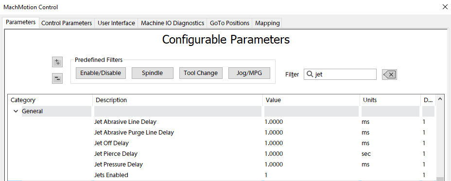
You may try setting the Jet Abrasive Purge Line Delay at 1250 ms which allows the abrasive to stop flowing just before the water turns off. I also set the Jet Off Delay to 250 ms which gives us a slight pause after the water turns off and before it starts moving to the next cut.
IO Setup
Virtually every waterjet will need some of following signals. Map each of the ones you need to the correct output.

| Name | Function | Configuration |
| Jet Abrasive Output(s) | Turns on and off abrasive for the corresponding jet. | Map it to the correct output signal in Mach. |
| Jet High Pressure Output(s) | Turns on and off high pressure for the corresponding jet. Also called things like UHP On/On valve. | |
| Jet Pressure Output(s) | Turns on and off the actual jet. Often called Water On or Jet On. | |
| Jet Pump Output | This turns on the actual intensifier pump. If using a PLC this should trigger the PLC to start the intensifier. Often called Intensifier. |
Some waterjets may have some of these more advanced IO. This is more for when the intensifier is controlled inside the MachMotion PLC.
Outputs
| Name | Function | Configuration |
| HP Bleeddown Valve | When the jet turns off this valve must open to let the pressure out of the line. Should always be off when the intensifier is off. | Setup in the PMC. |
| Cooling Water Shutoff Valve |
This function keeps the pump cool. Should always be on when the pump is on. |
Setup in the PMC. |
| Filtered Water / Water Inlet | This sends water to the intensifier. It must be on before the intensifier is turned on or it could blow it up. | Setup in the PMC. |
| INTENSIFIER LEFT SHIFT SOLENOID | Moves the hydraulic cylinder to the left. | Must be wired to the PLC and programmed in the PLC. |
| INTENSIFIER Right SHIFT SOLENOID | Moves the hydraulic cylinder to the right. | Must be wired to the PLC and programmed in the PLC. |
Inputs
| Name | Function | Configuration |
| Garnet Empty | Tells the operator when to refill the garnet |
Setup in GMS. |
| INTENSIFIER LEFT CHECK VALVE OVERTEMP |
Setup in GMS. | |
| INTENSIFIER RIGHT CHECK VALVE OVERTEMP |
Setup in GMS. |
|
| INTENSIFIER LEFT SHIFT SENSOR |
Must be wired to the PLC and programmed in the PLC. |
|
| INTENSIFIER RIGHT SHIFT SENSOR |
Must be wired to the PLC and programmed in the PLC. |
|
| INLET WATER PRESSURE WARNING |
Setup in GMS. |
|
| INLET WATER PRESSURE SHUTDOWN | This input measures the water pressure at the intensifier after the water inlet motor or pump is on. It must be up to pressure before the intensifier can turn on. |
Setup in GMS. AND must be wired to the PLC to prevent the Intensifier from turning on until this input is off. |
| HP BLEEDDOWN OVERTEMP WARNING |
Setup in GMS. |
|
| HYDRAULIC OIL OVERTEMP WARNING |
Setup in GMS. |
|
| HYDRAULIC OIL OVERTEMP SHUTDOWN |
Setup in GMS. |
|
| HYDRAULIC OIL LEVEL SHUTDOWN |
Setup in GMS. |
Some waterjets have a servo controlled Abrasive. For that use these settings:

Analog Inputs and Outputs
You may have analog inputs and outputs used for setting pressure or garnet speed. Often you put them on the main screen of the waterjet. Configure them according to the device you are using (Siemens PLC Setup, or Rapidpath Beckhoff Setup).


PLC Setup
If the intensifier is controlled by the MachMotion PLC, then you need to program the PLC.
Before programming the PLC, make sure to test all the machine IO in Mach. That allows you to easily confirm the IO is working.
Then program the PLC with our default PLC program for waterjets. It is located under development SVN: C:\Mach4_Development\PLCs\PLC-Program-Generic-Waterjet-Intensifier-Pump-Control_V15 .
Now you need to remove the outputs in Mach so only the PLC can write to them.
Open the Modbus window and delete the outputs that can only be controlled by the PLC:

For example, remove intensifier left solenoid and right solenoid that are mapped to Q0.0 and Q0.1 by clicking on output and then selecting Remove a Modbus Function button.


Some waterjets may need some slight modifications. You can make them here.
Testing PLC Intensifier
You can monitor the PLC and make sure that the intensifier is cycling back and forth.