2000 Series Surface Grinder Operating Manual
![]()
1. Introduction
1.1 Control Startup
To open the control software double-click on the profile icon on the desktop.

1.2 Overview
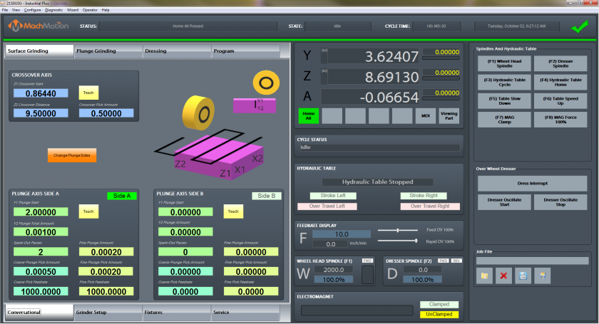
This manual gives the process for basic operation of a using the 2000 Series Surface Grinder MachMotion control. The screen is shown below, followed by a brief summary of the different features of the screen.

1.2.1 Conversational
The conversational screens are used to do your specific grinding functions. You can surface grind, plug grind, and dress. Traverse grind is also coming soon. For advanced mode you can even program your own cycles in the [Program] tab.
1.2.2 Grinder Setup
Grinder setup is used to set up your wheel, dresser options, and safety clearances.
1.2.3 Fixtures
Fixtures are onlyis used for advancedsetting usersup whenthe manuallystarting adjustingposition settings.of a part.
1.2.4 Service
Service is used for setting up the machine, diagnostics, and getting remote help from MachMotion's support team.
1.2.5 Screen Panel
This contains your current axis positions, the status, hydraulic table feedback, feed rates and spindle speeds. On the widget panel on the very left you can set up user buttons for your specific machine according to your preference.
Note that the grind table can be hydraulic or servo controlled.
2. Conversational
The conversational screens are used to do your specific grinding functions. You can surface grind, plug grind, and dress. For advanced mode you can even program your own cycles in the [Program] tab.
Surface Grinding
Surface grinding is used to grind a flat plane. You can use it to grind both sides of the same part by selecting [Gange Plunge Sides.Sides].

Start by entering in the data for the Crossover Axis.
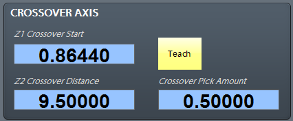
[Z1 Crossover Start] is the position the grind will start from and it will go the [Z2 Crossover Distance] from the start position (it is an incremental position). You can enter in a positive or negative value depending on what direction you want to go.
Use the axis graphics to see which directions the machine will move.

Next enter in the data for Side A and / or Side B to show how much the grinder should plunge.

[Y1 Plunge Start] is the position the grind will start from in the Y axis and it will go the [Y2 Plunge Total Amount] from the start position (it is an incremental position). You can enter in a positive or negative value depending on what direction you want to go.
[Spark-Out Passes] is the number of times the machine will repeat the cycle without lowering the Y axis at the end of the cycle.
[Fine Plunge Amount] is the amount of material to take off in fine grind. It is the distance from the end of the grind location. If you do not want a fine grind, set it to 0.
[Course Plunge Pick Amount] is the amount to take off per pass while doing a course grind.
[Fine Plunge Pick Amount] is the amount to take off per pass while doing a fine grind.
Plunge Grinding
Plunge grind is used to plunge in either Y or Z direction. It is similar to the surface grinding other than that you are only moving in one axis.

Dressing
The [Dressing] tab allows you to configure your dressing cycle.

You can select between a [Over Wheel Dress] or a [Straight Dress] cycle.
The dress cycle will take off the [Dress Amount] each pass up to [Dress Passes] value.
The [Dress Compensation Factor] is the percentage of how the machine will actually comp for each dress. Even though you may dress 0.020", if the control lowered the Y axis by 0.020" your parts might come out too small. The [Dress Compensation Factor] tells the machine how much of the total dress amount to actually lower your Y axis by.
Program
In the [Program] tab you can view the tool path display of what you are cutting or load in your own custom program.

You can load in your own files by selecting file Load.

Tool Path Screen
Below are the controls to manipulate the tool path screen:
- Zoom – Right click with the mouse and move mouse up/down or using the scroll wheel on the mouse
- Rotate – Left click with the mouse and rotate the part by moving the mouse
- Pan – Press and hold [Ctrl] on the keyboard and left click with the mouse, then pan by moving the mouse (one-hand control option is to use left and right mouse click and move the mouse. No [Ctrl] press needed)
3. Grinder Setup
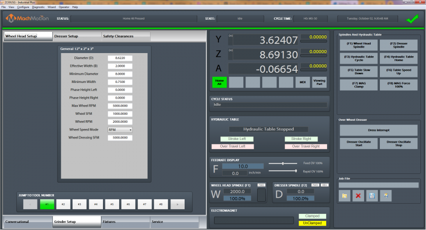
Wheel Head Setup
The wheel head setup is the location to setup all the parameters for your wheel head.

The following parameters are the most important:
Diameter (D) - This is used to keep track of the wheel diameter as you dress and the machine will automatically compensate the wheel diameter.
Effective Width (B) - This is the width that the grinding wheel can actually grind with.
Wheel FPM - This is the commanded wheel head speed in Surface Feet per Minute.
Wheel RPM - This is the commanded wheel head speed in Rotations per Minute.
Wheel Speed Mode - Here you select if you want to use Rotations per Minute (RPM) or Surface Feet per Minute (SFM).
Dresser Setup
Select the type of dresser you will be using and then simply teach the diamond location by pressing the [Teach] buttons. Then each time you tell the machine to dress it will remember those locations and automatically dress your wheel head.

Safety Clearances
Safety positions are used for the clearance values when dressing.

4. Fixture Offsets
To set up a new program, go to the [Fixtures] tab. Position your axes to the starting location of your part. Then press the zero buttons to set your part zero.

For example, once the machine is at the desired zero position in the Z axis, zero it by pressing the [Zero Z] button.

5. Service
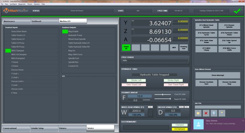

For example, in the [Machine I/O] tab, you can view the state of the I/O on the machine. For troubleshooting you can double click on any output and it will activate.
Setup and support can be accessed by the [Maintenance] tab.
5.6. Homing
To home the Machine, click [Cycle Start] when the control first comes up. The machine will enable and all the axes touch off the home sensors to find your previous starting position.

You can also begin by click the [Reset] button and thenbutton, the [Service] tabtab, the [Maintenance] tab, and then click on [Home All].
6.7. Programmed Movement
3.1 MDI
To command a movement using the MDI feature, press the [MDI] button.
Enter the desired G-Code command into the field and press [Cycle Start] to execute the command(s). The up/down arrow buttons will scroll through the history of cycled commands. Click the Red [X] to close the MDI window.

Example MDI Command
3.2 G-Code
The primary method of commanding motion is using G-Code files. G-Code files can be hand written, generated by a wizard, or generated from CAD files using a CAM program.
3.2.6 Tool Path Screen
Below are the controls to manipulate the tool path screen:
Zoom – Right click with the mouse and move mouse up/down or using the scroll wheel on the mouseRotate – Left click with the mouse and rotate the part by moving the mousePan – Press and hold [Ctrl] on the keyboard and left click with the mouse, then pan by moving the mouse (one-hand control option is to use left and right mouse click and move the mouse. No [Ctrl] press needed)
7.8. Wheel Head
5.1You G-Codecan Spindlesee Controlthe current commanded speed and override on the right side of the screen.

The spindlewheel RMP is controlled through G-Code using the M-Codes M3 (Clockwise), M4 (Counterclockwise), and M5 (Off). To control the spindle speed in RPMs an S word is added.
For example, M3 S2000 would turn the spindle onsetup in the clockwiseWheel directionHead atSetup 2000tab RPM.
5.2section Manual3 Spindle Controlabove).
To control the spindlewheel head separately from G-Code use the spindle control on the operating panel. The [Spindle FWD] turns the spindlewheel head on clockwise and the [Spindle REV] turns the spindlewheel head on counterclockwise.

Spindle Control
The following spindle settings are also shown on the Spindle tab located in Configure -> Control -> Spindle:
G50 Speed Limit – the maximum RPM the spindle can move with the current G50 settingRange – Pulley number selected and speed range
5.3 Spindle Display
The current spindle settings are shown in the main Spindle Display.

Spindle Display
S – Commanded SpeedSpindle OV – Spindle Override PercentageSpindle Load – % of the load of the spindle.Range – Current Pulley Selected
7. Fixture Offsets
All G-Code files have their own coordinate system. In order to allow parts to be located on the table at any desired location, the part offset can be defined to adjust the actual location of the part on the table.
Part offsets can be defined and saved using G54-G59P120. The functionality is designed to allow different tooling setups to have predefined zero points to allow for streamlined setup.
You can view the fixture table and change the values directly by clicking the [Fixtures] tab. The values can also be set by using the MDI command to select the G-Code number for the fixture offsets to be stored in. Once the machine is at the desired zero position, zero Z by pressing the [Zero Z] button.
Fixture Offsets
8.9. Appendix
8.1 Start-Up Procedure

Start-Up Procedure
8.2 Warranty Information
MachMotion warranty policy is subject to change. Updated information is available at our website:
https://machmotion.com/warranty
8.3 Additional Resources
Additional manuals and resources can be found at MachMotion.com
The MachMotion Team
http://www.machmotion.com
14518 County Road 7240, Newburg, MO 65550
(573) 368-7399 • Fax (573) 341-2672