2000 Series Surface Grinder Operating Manual
![]()
1. Introduction
1.1 Control Startup
To open the control software double-click on the profile icon on the desktop.
![]()
Control Icon
1.2 Overview
This manual gives the process for basic operation of a using the 2000 Series Surface Grinder MachMotion control. The screen is shown below, followed by a brief summary of the different features of the screen.

1.2.1 Conversational
The numberconversational shownscreens are used to do your specific grinding functions. You can surface grind, plug grind, and dress. For advanced mode you can even program your own cycles in the screenshotProgram referstab.
1.2.2 Grinder Setup
Grinder setup is used to aset briefup descriptionyour belowwheel, dresser options, and safety clearances.
1.2.3 Fixtures
Fixtures are only used for advanced users when manually adjusting settings.
1.2.4 Service
Service is used for setting up the image.machine, diagnostics, and getting remote help from MachMotion's support team.
Control
1.2.5 Screen Overview:
Gcode Tab
Panel
.jpg)
- contains
ToolyourPathcurrent- axis
Regen ToolPath - Refreshpositions, thetoolpathstatus, hydraulic table feedback, feed rates and spindle speeds. On the widget panel on the very left you can set up user buttons for your specific machine according to your preference.Note that the grind table can be hydraulic or servo controlled.
2. Conversational
Surface Grinding
Surface grinding is used to grind a flat plane. You can use it to grind both sides of the
gcodesame ViewpartTopby-selectingTopGangeviewPlungeofSides.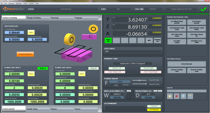
Start by entering in the
partdata ViewforISOthe-Crossover
FileZ1
- Crossover
RecentStart-isLoadtheapositionrecentlytheloadedgrindgcodewillprogramstart Loadfrom-andLoaditawillprogramgo the Z2 Crossover Distance from thecomputerstart position (it is an incremental position). You can enter in a positive orflashnegativedrivevalue Editdepending-onEditwhat direction you want to go.Use the
codeaxisthatgraphicsistoloadedseeintowhich directions thesoftwaremachine Closewill-move.Close
thegcodeNext
that is currently loadedenter in thesoftwaredata
Side ControlA- and
Cycle/Startor-SideStartsB to show how much thegcodegrinderfromshouldfromplunge.the beginning of the partFeed Hold - Pauses the gcode program and keeps the spindle runningCycle Stop - Stops the gcode program from runningReset - Resets the alarm and also enables the machine
StatusStatus - Displays any current messages (Home All Pressed, Cycle Start Pressed, etc.)State - Displays the current state of the machine (Run, Feedhold, etc)Cycle Time - Displays how long the gcode has been runningDate - Date and time of the timezone of the control
DROs (Axis Digital Readouts)MDI - Opens up a window that allows for gcode commandsViewing Part - Shows the part coordinates or machine coordinates of the machine
Active ModalsActive Offset - Shows the current active fixture offset (G54, G55, etc)
Tool DisplayT - The current tool number selectedNext Tool - The next tool that the gcode will needDiameter - Diameter of the toolLength - Length of the tool
Feedrate DisplayF - The current feedrate commandedFeed OV - The current Feedrate Override utilizing the Feedrate Override knob on the operating panel (0-200%)Rapid OV - The current Rapid Override utilizing the Rapid Override knob on the operating panel (0-200%)
Spindle DisplayS - The current spindle speedTSpeed - The current spindle speed feedbackFWD - Turns on if the spindle is moving ForwardREV - Turns on if the spindle is moving in ReverseSpindle OV - The current spindle override utilizing the spindle override knob on the operating panel (0-200%)Spindle Load - The current spindle load utilizing the spindle speed feedbackRange - Displays the current spindle range (spindle pulley)
AdvancedSingle Block - If active the software will go line by line through the gcode when you press the cycle start buttonBlock Delete - Deletes the block of gcode that is selectedPart Counter - Displays the number of parts that the machine has producedM1 OPT Stop - If active the software will stop at any M1 commands in the gcode program and waits for cycle startAlexsys - Opens up the conversational assistant Alexsys in another windowDry Run - If active the software will ignore all mist or flood commandsM-S-T Lock - If active the software will ignore all Macro codes, Spindle codes and Tool commandsFile Resume - If selected this will start the program at the selected gcode line and resumes the fileCollapse v - If selected this will minimize the Advanced buttons


Tools Tab
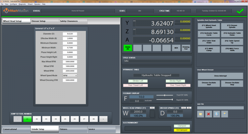
3. Grinder Setup

Edit4.
Edit Offsets - View and edit fixture offsets
ToolsTool Table - View and edit tool table
PocketsRegister Tools - Register and save tools
CalibrateTool Setters -
Tool Life ManagementCurrent Group -Next Group -Selected Group -Current Tool Life -Current Tool Count -Tool Life Remaining -Override Percentage -
Jump to Tool Number1,2,3,4 etc. - Tool number (Tool change)
ControlCycle Start - Starts the gcode from from the beginning of the partFeed Hold - Pauses the gcode program and keeps the spindle runningCycle Stop - Stops the gcode program from runningReset - Resets the alarm and also enables the machine
StatusStatus - Displays any current messages (Home All Pressed, Cycle Start Pressed, etc.)State - Displays the current state of the machine (Run, Feedhold, etc)Cycle Time - Displays how long the gcode has been runningDate - Date and time of the timezone of the control
DROs (Axis Digital Readouts)MDI - Opens up a window that allows for gcode commandsZero - Zero out the DROs for part coordinatesViewing Part - Shows the part coordinates or machine coordinates of the machine
Active ModalsActive Offset - Shows the current active fixture offset (G54, G55, etc)
Tool DisplayT - The current tool number selectedNext Tool - The next tool that the gcode will needDiameter - Diameter of the toolLength - Length of the tool
Feedrate DisplayF - The current feedrate commandedFeed OV - The current Feedrate Override utilizing the Feedrate Override knob on the operating panel (0-200%)Rapid OV - The current Rapid Override utilizing the Rapid Override knob on the operating panel (0-200%)
Spindle DisplayS - The current spindle speedTSpeed - The current spindle speed feedbackFWD - Turns on if the spindle is moving ForwardREV - Turns on if the spindle is moving in ReverseSpindle OV - The current spindle override utilizing the spindle override knob on the operating panel (0-200%)Spindle Load - The current spindle load utilizing the spindle speed feedbackRange - Displays the current spindle range (spindle pulley)
Fixtures Tab - Manual Setup
Service

EditEdit Offsets - View and edit fixture offsets
FixturesFixtures Table - View and edit fixture table (G54, G55, G56, etc.)
X/Y Edge Finder OffsetX+ -X- -Y+ -Y- -Edge Finder Diameter -
Fixture OffsetsX, Y, Z, etc. -
Rotary AxisX,Y, Z -
ControlCycle Start - Starts the gcode from from the beginning of the partFeed Hold - Pauses the gcode program and keeps the spindle runningCycle Stop - Stops the gcode program from runningReset - Resets the alarm and also enables the machine
StatusStatus - Displays any current messages (Home All Pressed, Cycle Start Pressed, etc.)State - Displays the current state of the machine (Run, Feedhold, etc)Cycle Time - Displays how long the gcode has been runningDate - Date and time of the timezone of the control
DROs (Axis Digital Readouts)MDI - Opens up a window that allows for gcode commandsZero - Zero out the DROs for part coordinatesViewing Part - Shows the part coordinates or machine coordinates of the machine
Active ModalsActive Offset - Shows the current active fixture offset (G54, G55, etc)
Tool DisplayT - The current tool number selectedNext Tool - The next tool that the gcode will needDiameter - Diameter of the toolLength - Length of the tool
Feedrate DisplayF - The current feedrate commandedFeed OV - The current Feedrate Override utilizing the Feedrate Override knob on the operating panel (0-200%)Rapid OV - The current Rapid Override utilizing the Rapid Override knob on the operating panel (0-200%)
Spindle DisplayS - The current spindle speedTSpeed - The current spindle speed feedbackFWD - Turns on if the spindle is moving ForwardREV - Turns on if the spindle is moving in ReverseSpindle OV - The current spindle override utilizing the spindle override knob on the operating panel (0-200%)Spindle Load - The current spindle load utilizing the spindle speed feedbackRange - Displays the current spindle range (spindle pulley)
Fixtures Tab - Probing Setup

SettingsX/Y Reposition Distance -Z Reposition Distance -Approach Distance -Retract Distance -Zero after Probe -Measure Only -
RoutinesControlCycle Start - Starts the gcode from from the beginning of the partFeed Hold - Pauses the gcode program and keeps the spindle runningCycle Stop - Stops the gcode program from runningReset - Resets the alarm and also enables the machine
StatusStatus - Displays any current messages (Home All Pressed, Cycle Start Pressed, etc.)State - Displays the current state of the machine (Run, Feedhold, etc)Cycle Time - Displays how long the gcode has been runningDate - Date and time of the timezone of the control
DROs (Axis Digital Readouts)MDI - Opens up a window that allows for gcode commandsZero - Zero out the DROs for part coordinatesViewing Part - Shows the part coordinates or machine coordinates of the machine
Active ModalsActive Offset - Shows the current active fixture offset (G54, G55, etc)
Tool DisplayT - The current tool number selectedNext Tool - The next tool that the gcode will needDiameter - Diameter of the toolLength - Length of the tool
Feedrate DisplayF - The current feedrate commandedFeed OV - The current Feedrate Override utilizing the Feedrate Override knob on the operating panel (0-200%)Rapid OV - The current Rapid Override utilizing the Rapid Override knob on the operating panel (0-200%)
Spindle DisplayS - The current spindle speedTSpeed - The current spindle speed feedbackFWD - Turns on if the spindle is moving ForwardREV - Turns on if the spindle is moving in ReverseSpindle OV - The current spindle override utilizing the spindle override knob on the operating panel (0-200%)Spindle Load - The current spindle load utilizing the spindle speed feedbackRange - Displays the current spindle range (spindle pulley)
EditEdit Offsets - View and edit fixture offsets
FixturesFixtures Table - View and edit fixture table (G54, G55, G56, etc.)
Service Tab - Maintenance

LimitsSoft Limits - Toggles software limits on or offLimit Override - Toggles to allow for the machine to move off a limit switch
PLCReset Pocket -PLC Sequence -
EnableDisable - Toggles if the machine is enabled or disabled
SettingsInterface Config -Motion Controller - Opens the plugin for the Motion ControllerScreen Config - Edit the screen layoutIndustrial Theme -Toggle Menu - Turns the menu on or offCompile Scripts - Refreshes (recompiles) programming scripts
HomingHome X - Homes the X axisHome Y - Homes the Y axisHome Z - Homes the Z axisHome All - Homes all axes
SupportRemote Support - Starts a remote support session with MachMotion Technical SupportSupport - Opens up the online MachMotion Support LibraryUpdates - Checks for updates for MachMotion SoftwareHistory - Views status history and alarms
UserLogout - Logs out of the Windows usernamePower - Turns off the computer
StatusStatus - Displays any current messages (Home All Pressed, Cycle Start Pressed, etc.)State - Displays the current state of the machine (Run, Feedhold, etc)Cycle Time - Displays how long the gcode has been runningDate - Date and time of the timezone of the control
DROs (Axis Digital Readouts)MDI - Opens up a window that allows for gcode commandsZero - Zero out the DROs for part coordinatesViewing Part - Shows the part coordinates or machine coordinates of the machine
Active ModalsActive Offset - Shows the current active fixture offset (G54, G55, etc)
Tool DisplayT - The current tool number selectedNext Tool - The next tool that the gcode will needDiameter - Diameter of the toolLength - Length of the tool
Feedrate DisplayF - The current feedrate commandedFeed OV - The current Feedrate Override utilizing the Feedrate Override knob on the operating panel (0-200%)Rapid OV - The current Rapid Override utilizing the Rapid Override knob on the operating panel (0-200%)
Spindle DisplayS - The current spindle speedTSpeed - The current spindle speed feedbackFWD - Turns on if the spindle is moving ForwardREV - Turns on if the spindle is moving in ReverseSpindle OV - The current spindle override utilizing the spindle override knob on the operating panel (0-200%)Spindle Load - The current spindle load utilizing the spindle speed feedbackRange - Displays the current spindle range (spindle pulley)
Service Tab - Dashboard

StatusStatus - Displays any current messages (Home All Pressed, Cycle Start Pressed, etc.)State - Displays the current state of the machine (Run, Feedhold, etc)Cycle Time - Displays how long the gcode has been runningDate - Date and time of the timezone of the control
DROs (Axis Digital Readouts)MDI - Opens up a window that allows for gcode commandsZero - Zero out the DROs for part coordinatesViewing Part - Shows the part coordinates or machine coordinates of the machine
Active ModalsActive Offset - Shows the current active fixture offset (G54, G55, etc)
Tool DisplayT - The current tool number selectedNext Tool - The next tool that the gcode will needDiameter - Diameter of the toolLength - Length of the tool
Feedrate DisplayF - The current feedrate commandedFeed OV - The current Feedrate Override utilizing the Feedrate Override knob on the operating panel (0-200%)Rapid OV - The current Rapid Override utilizing the Rapid Override knob on the operating panel (0-200%)
Spindle DisplayS - The current spindle speedTSpeed - The current spindle speed feedbackFWD - Turns on if the spindle is moving ForwardREV - Turns on if the spindle is moving in ReverseSpindle OV - The current spindle override utilizing the spindle override knob on the operating panel (0-200%)Spindle Load - The current spindle load utilizing the spindle speed feedbackRange - Displays the current spindle range (spindle pulley)
DashboardDashboard -
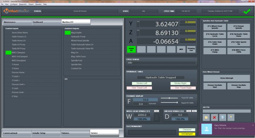
Service Tab - Machine I/O

StatusStatus - Displays any current messages (Home All Pressed, Cycle Start Pressed, etc.)State - Displays the current state of the machine (Run, Feedhold, etc)Cycle Time - Displays how long the gcode has been runningDate - Date and time of the timezone of the control
DROs (Axis Digital Readouts)MDI - Opens up a window that allows for gcode commandsZero - Zero out the DROs for part coordinatesViewing Part - Shows the part coordinates or machine coordinates of the machine
Active ModalsActive Offset - Shows the current active fixture offset (G54, G55, etc)
Tool DisplayT - The current tool number selectedNext Tool - The next tool that the gcode will needDiameter - Diameter of the toolLength - Length of the tool
Feedrate DisplayF - The current feedrate commandedFeed OV - The current Feedrate Override utilizing the Feedrate Override knob on the operating panel (0-200%)Rapid OV - The current Rapid Override utilizing the Rapid Override knob on the operating panel (0-200%)
Spindle DisplayS - The current spindle speedTSpeed - The current spindle speed feedbackFWD - Turns on if the spindle is moving ForwardREV - Turns on if the spindle is moving in ReverseSpindle OV - The current spindle override utilizing the spindle override knob on the operating panel (0-200%)Spindle Load - The current spindle load utilizing the spindle speed feedbackRange - Displays the current spindle range (spindle pulley)
Machine I/OEnabled Inputs -Enabled Outputs -I/O -
2.5. Homing
To home the Machine, begin by click the [Reset] button and then the [Service] tab and click on [Home All].
3.6. Programmed Movement
3.1 MDI
To command a movement using the MDI feature, press the [MDI] button.
Enter the desired G-Code command into the field and press [Cycle Start] to execute the command(s). The up/down arrow buttons will scroll through the history of cycled commands. Click the Red [X] to close the MDI window.

Example MDI Command
3.2 G-Code
The primary method of commanding motion is using G-Code files. G-Code files can be hand written, generated by a wizard, or generated from CAD files using a CAM program.
3.2.6 Tool Path Screen
Below are the controls to manipulate the tool path screen:
- Zoom – Right click with the mouse and move mouse up/down or using the scroll wheel on the mouse
- Rotate – Left click with the mouse and rotate the part by moving the mouse
- Pan – Press and hold [Ctrl] on the keyboard and left click with the mouse, then pan by moving the mouse (one-hand control option is to use left and right mouse click and move the mouse. No [Ctrl] press needed)
4.7. ToolsWheel and Tool Offsets
4.1 Tool Offsets
4.2 Tool Setup
5. Spindle ControlHead
5.1 G-Code Spindle Control
The spindle is controlled through G-Code using the M-Codes M3 (Clockwise), M4 (Counterclockwise), and M5 (Off). To control the spindle speed in RPMs an S word is added.
For example, M3 S2000 would turn the spindle on in the clockwise direction at 2000 RPM.
5.2 Manual Spindle Control
To control the spindle separately from G-Code use the spindle control on the operating panel. The [Spindle FWD] turns the spindle on clockwise and the [Spindle REV] turns the spindle on counterclockwise.

Spindle Control
The following spindle settings are also shown on the Spindle tab located in Configure -> Control -> Spindle:
- G50 Speed Limit – the maximum RPM the spindle can move with the current G50 setting
- Range – Pulley number selected and speed range
5.3 Spindle Display
The current spindle settings are shown in the main Spindle Display.

Spindle Display
- S – Commanded Speed
- Spindle OV – Spindle Override Percentage
- Spindle Load – % of the load of the spindle.
- Range – Current Pulley Selected
6. Machine Output Control
7. Fixture Offsets
All G-Code files have their own coordinate system. In order to allow parts to be located on the table at any desired location, the part offset can be defined to adjust the actual location of the part on the table.
Part offsets can be defined and saved using G54-G59P120. The functionality is designed to allow different tooling setups to have predefined zero points to allow for streamlined setup.
You can view the fixture table and change the values directly by clicking the [Fixtures] tab. The values can also be set by using the MDI command to select the G-Code number for the fixture offsets to be stored in. Once the machine is at the desired zero position, zero Z by pressing the [Zero Z] button.

Fixture Offsets
8. Appendix
8.1 Start-Up Procedure

Start-Up Procedure
8.2 Warranty Information
MachMotion warranty policy is subject to change. Updated information is available at our website:
https://machmotion.com/warranty
8.3 Additional Resources
Additional manuals and resources can be found at MachMotion.com
The MachMotion Team
http://www.machmotion.com
14518 County Road 7240, Newburg, MO 65550
(573) 368-7399 • Fax (573) 341-2672