2000 Series Surface Grinder Operating Manual
![]()
1. Introduction
1.1 Control Startup
To open the control software double-click on the profile icon on the desktop.

1.2 Overview
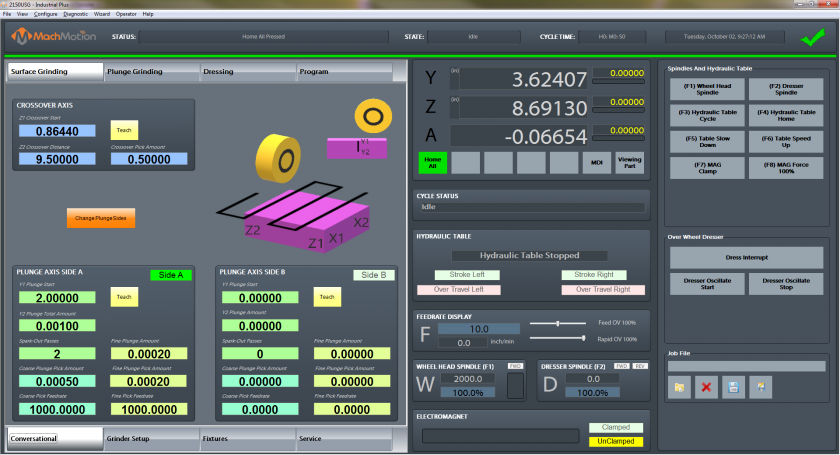
This manual gives the process for basic operation of a using the 2000 Series Surface Grinder MachMotion control. The screen is shown below, followed by a brief summary of the different features of the screen.

1.2.1 Conversational
The conversational screens are used to do your specific grinding functions. You can surface grind, plug grind, and dress. For advanced mode you can even program your own cycles in the Program tab.
1.2.2 Grinder Setup
Grinder setup is used to set up your wheel, dresser options, and safety clearances.
1.2.3 Fixtures
Fixtures are only used for advanced users when manually adjusting settings.
1.2.4 Service
Service is used for setting up the machine, diagnostics, and getting remote help from MachMotion's support team.
1.2.5 Screen Panel
This contains your current axis positions, the status, hydraulic table feedback, feed rates and spindle speeds. On the widget panel on the very left you can set up user buttons for your specific machine according to your preference.
Note that the grind table can be hydraulic or servo controlled.
2. Conversational
Surface Grinding
Surface grinding is used to grind a flat plane. You can use it to grind both sides of the same part by selecting Gange Plunge Sides.
Start by entering in the data for the Crossover Axis.
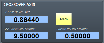
Z1 Crossover Start is the position the grind will start from and it will go the Z2 Crossover Distance from the start position (it is an incremental position). You can enter in a positive or negative value depending on what direction you want to go.
Use the axis graphics to see which directions the machine will move.

Next enter in the data for Side A and / or Side B to show how much the grinder should plunge.

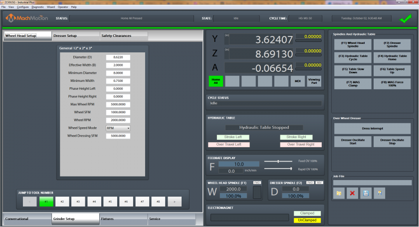
3. Grinder Setup
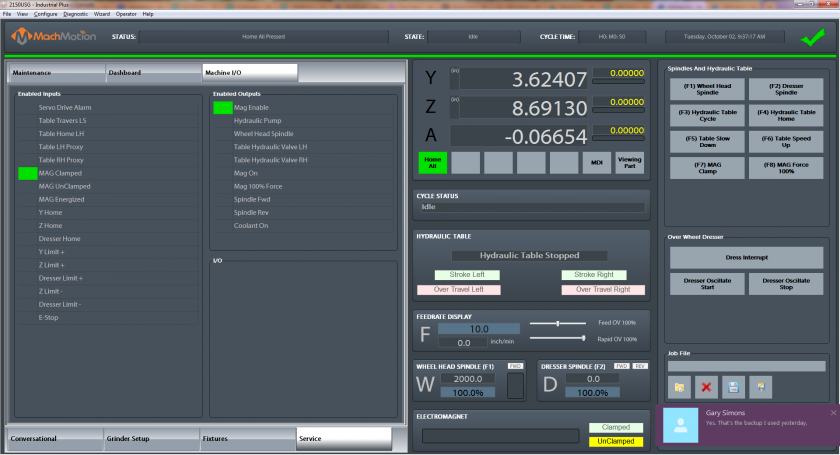
4. Service
5. Homing
To home the Machine, begin by click the [Reset] button and then the [Service] tab and click on [Home All].
6. Programmed Movement
3.1 MDI
To command a movement using the MDI feature, press the [MDI] button.
Enter the desired G-Code command into the field and press [Cycle Start] to execute the command(s). The up/down arrow buttons will scroll through the history of cycled commands. Click the Red [X] to close the MDI window.

Example MDI Command
3.2 G-Code
The primary method of commanding motion is using G-Code files. G-Code files can be hand written, generated by a wizard, or generated from CAD files using a CAM program.
3.2.6 Tool Path Screen
Below are the controls to manipulate the tool path screen:
- Zoom – Right click with the mouse and move mouse up/down or using the scroll wheel on the mouse
- Rotate – Left click with the mouse and rotate the part by moving the mouse
- Pan – Press and hold [Ctrl] on the keyboard and left click with the mouse, then pan by moving the mouse (one-hand control option is to use left and right mouse click and move the mouse. No [Ctrl] press needed)
7. Wheel Head
5.1 G-Code Spindle Control
The spindle is controlled through G-Code using the M-Codes M3 (Clockwise), M4 (Counterclockwise), and M5 (Off). To control the spindle speed in RPMs an S word is added.
For example, M3 S2000 would turn the spindle on in the clockwise direction at 2000 RPM.
5.2 Manual Spindle Control
To control the spindle separately from G-Code use the spindle control on the operating panel. The [Spindle FWD] turns the spindle on clockwise and the [Spindle REV] turns the spindle on counterclockwise.

Spindle Control
The following spindle settings are also shown on the Spindle tab located in Configure -> Control -> Spindle:
- G50 Speed Limit – the maximum RPM the spindle can move with the current G50 setting
- Range – Pulley number selected and speed range
5.3 Spindle Display
The current spindle settings are shown in the main Spindle Display.

Spindle Display
- S – Commanded Speed
- Spindle OV – Spindle Override Percentage
- Spindle Load – % of the load of the spindle.
- Range – Current Pulley Selected
7. Fixture Offsets
All G-Code files have their own coordinate system. In order to allow parts to be located on the table at any desired location, the part offset can be defined to adjust the actual location of the part on the table.
Part offsets can be defined and saved using G54-G59P120. The functionality is designed to allow different tooling setups to have predefined zero points to allow for streamlined setup.
You can view the fixture table and change the values directly by clicking the [Fixtures] tab. The values can also be set by using the MDI command to select the G-Code number for the fixture offsets to be stored in. Once the machine is at the desired zero position, zero Z by pressing the [Zero Z] button.
Fixture Offsets
8. Appendix
8.1 Start-Up Procedure

Start-Up Procedure
8.2 Warranty Information
MachMotion warranty policy is subject to change. Updated information is available at our website:
https://machmotion.com/warranty
8.3 Additional Resources
Additional manuals and resources can be found at MachMotion.com
The MachMotion Team
http://www.machmotion.com
14518 County Road 7240, Newburg, MO 65550
(573) 368-7399 • Fax (573) 341-2672