
Orion 3000 Controller
{{@672}}
This manual provides an overview the features of the Orion control.3000 controller.
1. Overview
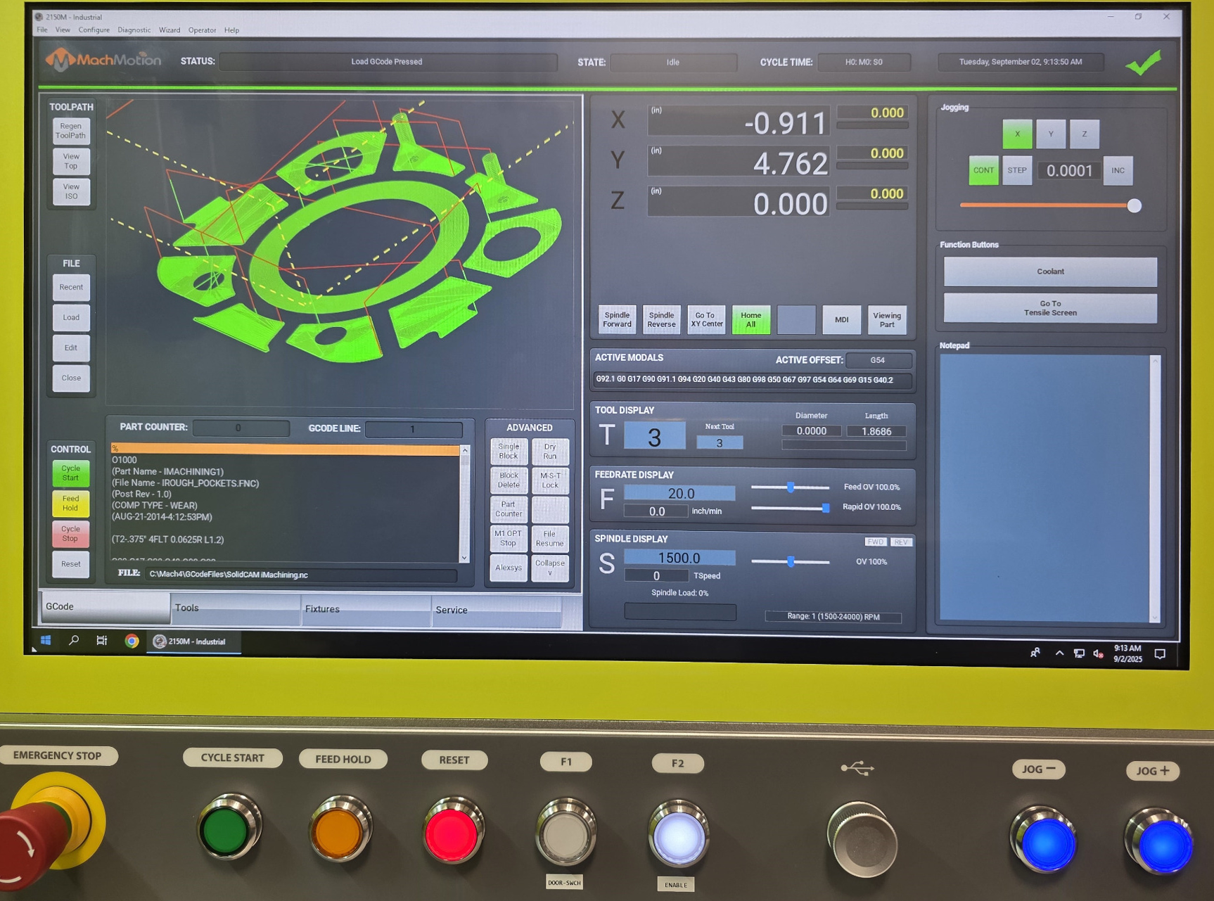
The Orion 3000 control is an industrial PC control with an integrated 21.5" touch screen and operator panel.
2. Connections
1. Machine interface
These are the only required connections to make to the control before you turn it on.
|
|
|
|
|
|
|
|
|
|
|
|
*Additional Estop buttons must be wired in series with this one.
2.User Available USB

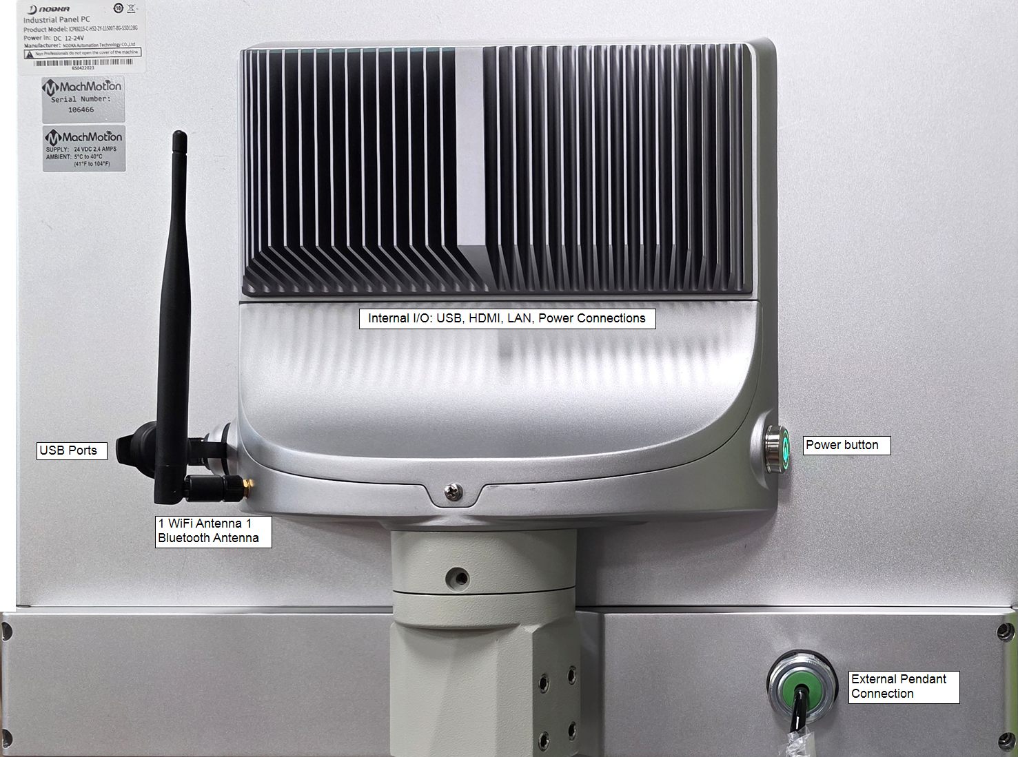
External USB on the face of the control for loading files with a Flash Drive or temporary use with any other auxiliary USB device. One External port underneath the keyboard tray for wireless keyboard and mouse.
3. Features
- 21.5” LCD,1920*1080,resolution,Multi-touch,Capacitive Touchscreen
- Full IP65 design
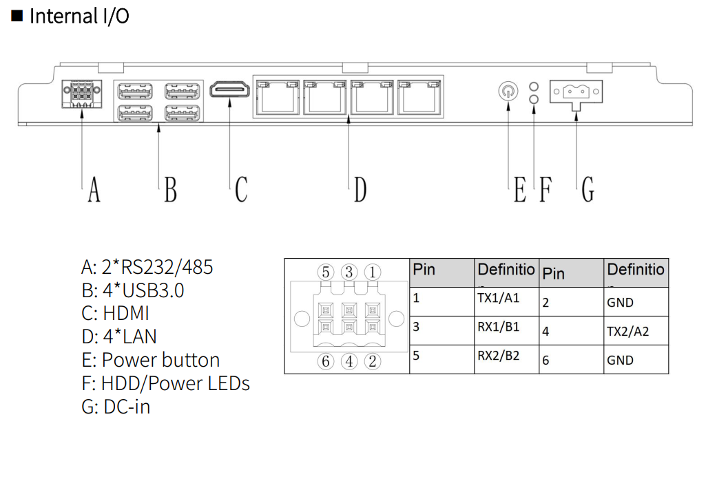
- 2/4*Glan/4*USB3.0/1*HDMI/2*COM
- DC12-24V power input
- Support ARM mounting from TOP side or BOTTOM side
- Fanless and anodized aluminum
3.4. Specifications
1.
| Category | ICP69215-C-H52-4Y | |
| LCD | Size | 21.5" LCD |
| Resolution ratio | 1920*1080 | |
| White Luminance | 250cd/m2 | |
| MTBF (hour) | 30000 hrs | |
| Contrast Ratio | 3000:1 | |
| Viewing Angle | (L)89 / (R)89 / (T)89 / (B)89 | |
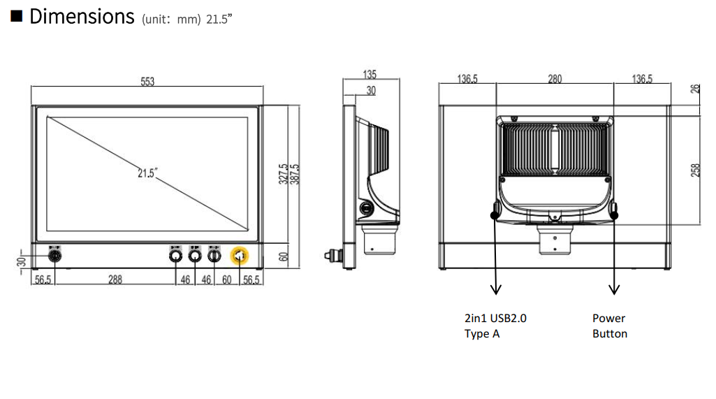
| Mechanical | Dimensions (W x H x D) | 553mm x 387.5mm x 135mm |
| Installation | Swing ARM mounting (Support NODKA 4460 square tube and Rittal CP 40) | |
| Buttons | Default: 1x Emergency, 1x selection, 1x red push, 1x green push, 1x Key switch | |
| Weight | 9.0 Kg | |
| System | CPU | Intel® Core™ 10-11th i5/i3, LGA1200, Max.35W |
| Memory | 2 x 260-pin DDR4 SODIMM, Max support 32GB | |
| Storage | 1 x 2.5" HDD/SSD + 1 x mSATA | |
| Network (LAN) | 4 x Intel 1000Mbps Ethernet | |
| HDMI | HDMI 1.2 | |
| Serial ports | 2 x RS232/485 (optional), 2 x 3-pin Phoenix Connector | |
| USB | 4 x USB (3.0/2.0/1.0) | |
| Touch screen | Touch screen type | Capacitive Touch screen |
| Communication interface | USB | |
| Transmittance | ≥87% | |
| OS | OS | Windows 7, Windows 10 IoT, Ubuntu, CentOS |
| Power Consumption | Input Voltage |
1x 2-pin Phoenix DC (internal); 1x power button with light (back) |
| Idle
|
Minimum
|
|
|
Operating
|
0°C ~ 50°C for SSD; 0°C ~ 45°C for HDD |
|
|
|
| 5~95% |
||
|
SSD
|
|
|
Operating
|
|
|
Class
|
|
| IP
|
| |
|
| |
| ||
|
| |
|
| |
|
| |
|
| |
|
| |
|
| |
|
| |
|
| |
| ||
|
| |
|
| |
|
| |
| ||
|
| |
2.
5. Mechanical Drawings
4.6. Operator Panel

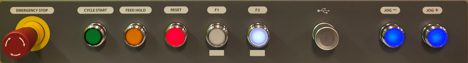
1.
Emergency Stop
Emergency Stop
2. Cycle Control
Cycle Start can be used to start a G-Code file and is also used to start other commands such as MDI and GoTo Commands.
Feed Hold is used to pause motion during file run and will leave the spindle on. Cycle start will resume motion and continue file execution.
3. Cycle Cancels
Retract is an optional feature, currently in development and not operational. Check in with MachMotion for more information!
Cycle stop does a full cancel of the file, turns off the spindle and coolant, and puts the machine in idle.
Reset is used to clear alarms and set the machine back to default modals. These defaults can be changed in the Initialization Codes sections of the default control configuration. Reset also does a full cycle stop and rewinds the GCode file.
4. Feed Rate Overrides
The Feedrate Override knob will modify Feedrate Override percentF1 and willF2 affect any G01 feed rate moves. The feedrate percentage value is shown on the screen. If you are expecting motion and nothing is going, verify your feedrate is not set to 0%.
The 4 Rapid Override buttons will set the Rapid Override percent and will affect any G00 rapid rate moves. The percentages for each can be changed in the X15-[##] Operator Panel settings. You can access this from the Service section, then Maintenance tab, then Interface Config button:
5. Spindle Control
Spindle control buttons let you directly set the spindle forward, backwards, and stop. These are equivalent to calling M3, M4, and M5. You can set a default spindle speed value that will be set any time the system is initialized (reset pressed) by adding S### (where ### is the desired speed) in the Initialization Codes sections of the default control configuration.
6. Function Buttons
7.
USB two USB A ports
Jog Selection
CONT will put all jogging into continues mode-willJog continue+ are integrated with on-screen controls where you can select the axis to jog as long as you hold the jog button.
X1, X10, and X100 are incremental jogs and will move the incremental distances configured in Config -> Control
8. Jog Group
jogged