
Motion Filter Plugin
Introduction
Overview
The MotionFilter plugin transforms axis positions between the motion planner (the "core") and the physical motors. It lets one axis influence another — gearing a slave to a master, overriding one axis from another, compensating a mechanical squaring error, applying a rotational transform, or correcting a linear taper — without changing the part program. Every transform is applied on the fly as positions stream to the motors and is exactly reversed on the way back so the control always sees a consistent picture.
The plugin is machine-type agnostic. The same features work on mills, lathes, and grinders. Axes are referenced by index (0 = X, 1 = Y, 2 = Z, 3 = A, …), so any pairing that makes physical sense is allowed.
Feature Summary
| Feature | What it does |
| Gearing | A slave axis motor follows a master axis motor at a configurable ratio. The slave’s planner position is untouched; only its motor output is scaled and added. Ratio may be negative to invert direction. |
| Axis Override | Commanded motion on a secondary axis is copied onto a primary axis. Moving the primary directly adds no extra motion. |
| Taper Compensation | A slave axis is corrected as a linear function of a master axis: correction = ratio × (master − pivot). Used to correct an unwanted taper so a nominally straight feature comes out straight. |
| Squaring Compensation | Compensates a mechanical out-of-square error between two axes by moving a following axis as a function of an angled axis. |
| Rotation Filters | Rotational coordinate transforms between axis triplets. |
| Position Logging | High-throughput binary logging of every push/pop stage for offline analysis and diagnostics. |
| Adaptive Path Offset | A bounded, smooth offset along the path normal in X/Y, or along Z, driven by load feedback (spindle load, an axis load, or a register) plus operator bumps, that keeps the tool engaged in the material. Follows corners, arcs and stroke reversals; pre-engages from the last cut's average. |
How It Works
Push / Pop Model
The plugin sits in the position pipeline as a two-way filter:
- Push (planner → motors): transforms commanded positions before they reach the motors.
- Pop (motors → planner): the exact inverse transform, so the core sees positions consistent with what it commanded.
On push, the stages run in order: sync → rotation → gearing → squaring → axis override → taper comp. On pop they run in the reverse order. Because push and pop are exact inverses, enabling or disabling a filter never causes a position jump when the control re-synchronizes.
Push and pop must remain exact inverses. A mismatch shows up as a sudden position jump on the DRO the moment the core re-synchronizes. Every filter caches the value it applied on push and subtracts that same value on pop for this reason.
Smooth Engage / Disengage
Filters that can be turned on or off mid-program (gearing recovery, taper comp) never step an axis. When a correction needs to change, the affected axis is eased from its current value to the new target with a 5th-order S-curve trajectory — zero velocity and zero acceleration at both ends, so there is no audible “bang” and no jerk step.
Taper Compensation
Concept
Taper compensation corrects an unwanted taper. If a part that should be a straight cylinder comes out with a slightly larger diameter at one end — from workhead misalignment, deflection, or wheel wear — taper comp continuously offsets the infeed axis as a function of the traverse axis so the finished feature is straight. The part program stays straight; the control does the correcting.
The correction applied to the slave axis is:
correction = ratio × (master_machine_position − pivot)- Slave — the axis that receives the correction (X, the diameter/infeed axis, on an OD/ID grinder).
- Master — the axis the correction tracks (Z, the traverse axis).
- Ratio (Amount) — slave distance per one unit of master travel. Example:
0.005means X moves 0.005 for every 1.0 of Z travel. - Pivot — the master position where the correction is exactly zero. Set this to where the part was dialed in on size, so that point is left untouched and the rest is corrected around it.
On an OD/ID grinder you configure the X Axis taper comp with its master set to Z. The settings section is named for the slave (corrected) axis. Rule of thumb: the axis you would nudge to fix the diameter is the one you configure.
Pivot Anchoring
The pivot is captured as an absolute machine coordinate the moment comp is engaged and is never recomputed from live positions afterward. This means changing a work offset (G54…G59), re-zeroing, or motor drift while the machine is disabled does not move the pivot. The compensation stays anchored to the physical geometry, which is what keeps the dialed-in end on size.
Each axis has a Pivot Position Coordinate System setting:
- Part — the entered pivot is in part (work) coordinates and is converted to machine coordinates at engage time. On every tool change the pivot is automatically shifted by the new tool offset so it keeps following the part.
- Machine — the entered pivot is an absolute machine coordinate and is used verbatim, never adjusted.
The Arm Switch
Taper Comp Enabled is the overarching arm switch. It must be Yes for compensation to engage. When it is No, the M256 engage command becomes a silent no-op — a posted program still runs, just uncompensated — so the same program is portable to machines that do not use taper comp. Turning comp off (M257) is always honored regardless of the arm switch.
M-Codes
| M-code | Purpose |
| M256 | Engage (or update) taper compensation from the stored settings. Silent no-op when the arm switch is off. Blocks until the correction ramp settles so the next line runs fully compensated. |
| M257 | Disengage taper compensation. Ramps the correction to zero. Always honored. Idempotent. |
M256 optional words:
| Word | Meaning |
| Q | Pair selector: Q1 = X slave, Q2 = Y slave, Q3 = Z slave. Omitted = engage every configured pair. |
| P | Pivot position along the master, in part coordinates. Writes the stored Pivot setting, then engages. |
| R | Amount — slave distance per one unit of master travel. Writes the stored Amount setting, then engages. |
M257 optional word: Q selects a single pair to disengage (Q1/Q2/Q3); omitted disengages all active pairs.
The P and R words persist — they overwrite the stored settings, so a value posted by a program remains the machine’s taper setting after the program ends. Pair topology (which axes are paired) can only be changed in the settings, never from an M-code.
(Engage every configured pair from the stored settings)
M256

(X pair: 0.005 per unit of master, pivot at part zero, then engage)
M256 Q1 R0.005 P0

(Dress cycle choreography: comp off, dress, comp back on)
M257
G261 (dress)
M256

(Disengage all taper comp)
M257
Settings
Taper Comp settings live in the shared Common settings and appear under the Taper Comp category of the MachMotion configuration Parameters tab.
| Setting | Default | Range | Description |
| Taper Comp Enabled | No | Yes / No | Overarching arm switch. Must be Yes for comp to engage. |
| Ramp Speed — Percent | 25 | 1–100 % | Fraction of the slave axis max velocity and acceleration used by the engage / disengage / update ramp. |
| Ramp Minimum Duration | 0.5 | ≥ 0 s | Floor on the ramp duration. Lower it to make small corrections apply faster. |
| X/Y/Z Axis Taper Comp Configured | No | Yes / No | Enables that axis as a taper comp slave. |
| Master Axis That <axis> Follows | — | choice | Which of the other two axes is the master for this slave. |
| <axis> Distance Per One Unit Of Master Travel | 0 | float | The Amount (ratio). Signed. |
| Pivot — Position Along Master Where Correction Is Zero | 0 | float | The pivot position. |
| Pivot Position Coordinate System | Part | Part / Machine | Whether the pivot is part or machine coordinates (see Pivot Anchoring). |
Ramp Speed
The two ramp settings control different regimes of the same S-curve. For a given correction distance, the planner picks the shortest duration that respects all three limits: percent of max velocity, percent of max acceleration, and the minimum-duration floor.
- Ramp Speed Percent dominates large corrections — raise it toward 100 to apply big changes faster.
- Ramp Minimum Duration dominates small corrections — a tiny correction would otherwise apply almost instantly, so the floor keeps it smooth. Lower it toward zero to make small corrections snap in.
The ramp is always a quintic (5th-order) S-curve, so jerk is finite and continuous no matter how the two settings are chosen — there is no bang even at 100 % / 0 s.
Screen Controls
Four operator commands are available (assign them to buttons in the screen designer):
| Command | Action |
| Taper Comp Arm Toggle | Flips the arm switch. Disarming also disengages any active comp. Button LED reflects the armed state. |
| Taper Comp Adjust | Opens the adjust dialog (below). |
| Taper Comp On | Engages every configured pair from the stored settings. |
| Taper Comp Off | Disengages all pairs. |
The Taper Comp Adjust dialog shows the armed state, the active pair, and a live applied-correction readout with a color-coded state indicator (OFF / RAMPING / ACTIVE). The taper amount can be entered three ways — distance per unit, angle in degrees, or measured deviation over a length — and the resulting per-unit value is shown as you type. The pivot can be typed or captured from the current master position with Use Current. A Turn Comp On / Off button engages or disengages with exactly what the dialog shows; OK saves the settings (and ramps an update into an already-running comp).
If the Applied Correction reads 0 while the state shows ACTIVE, the master is simply sitting at the pivot — correction there is zero by definition. Jog the master away from the pivot and the applied value grows with distance.
Dressing Interaction
Dressing must run with comp off so the wheel is dressed straight (dresser positions are machine coordinates and would otherwise produce a tapered wheel). The wizard-posted program choreography is M257 before the dress cycle and M256 after it.
Adaptive Path Offset
Concept
Adaptive Path Offset adds a small, bounded offset to the programmed path so the tool is pushed into (or backed away from) the material without changing the part program. It was built for stone countertop polishing, where the programmed path is deliberately under-engaged and a spindle-load loop adds engagement until the load reaches a target, but the mechanism is generic: any process that wants a load-driven or operator-driven offset along the path normal can use it.
In XY mode the offset is applied perpendicular to the direction of the cut, on the side where the material is. In Z mode it is applied straight down into the material. The offset is a process-space correction, so it is applied before the machine-geometry stages (rotation, gearing, squaring, taper) and reversed exactly on the way back: the DROs keep showing the programmed path, and the offset survives mcMotionSync and disable / enable like every other stage.
Every change of the offset — turning on or off, the load loop, Engage In / Retract Out, the normal turning through a corner, a side change — goes through velocity- and acceleration-limited followers and a smoothing window, so the tool never steps. Turning off ramps the offset back to zero before the next programmed move.
Direction of Travel and the Offset Side
While the feature is enabled the plugin tracks the direction of travel from the motion points it is already receiving, even when the offset is off. The last direction of any motion and the last direction of feed motion are both published, so the side the offset will go to is known before it is turned on. The normal is always perpendicular to the current cut direction (rapids and jogs are ignored), it follows arcs and corners, and it holds through a reversal: on back-and-forth strokes along one edge the offset stays on the same physical side of the part.
The side is named as in cutter compensation, looking down with Z up and facing the direction of travel: 1 = left of travel (like G41), 2 = right of travel (like G42). It is chosen once, at turn-on (M275 Q1 / Q2, the NormalSide setting, or the tuning page); after that the plugin keeps the material on that side. Changing the side while on ramps the offset out, flips, and ramps back in. For sanding or polishing with the Z axis, M275 Q3 (Z down) or Q4 (Z up) puts the offset along Z instead; without a Q word the Mode and ZDownIsPositive settings apply.
| Contour | Program direction (from above) | Side |
| Outside perimeter | clockwise | Q2 (right) |
| Outside perimeter | counterclockwise | Q1 (left) |
| Sink cutout, inside | clockwise | Q1 (left) |
| Sink cutout, inside | counterclockwise | Q2 (right) |
Offset along the Z axis
For sanding or polishing a surface with the Z axis the offset is along Z instead of along the path normal: M275 Q3 engages downward (the tool is pressed into the surface below it) and M275 Q4 engages upward (the tool is pressed against a surface above it). There is no left or right in this mode, and the direction of travel in X/Y does not matter; the load loop, Engage In / Retract Out, the average engagement and the protection work exactly as in X/Y. Without a Q word the Mode setting selects X/Y or Z and ZDownIsPositive gives the sense. The Z limits are separate: MaxEngageZ / MaxRetractZ bound how far the offset may go in or out, and the soft limits of the Z axis still apply. With a Z axis load available from the drive, L3 makes the loop regulate on it (see Load Loop below).
| Q word | Mode | Offset direction |
| Q1 | X/Y | Left of travel (like G41); follows the path normal |
| Q2 | X/Y | Right of travel (like G42); follows the path normal |
| Q3 | Z | Z down: engagement pushes the tool down into the surface |
| Q4 | Z | Z up: engagement lifts the tool against a surface above |
| omitted | setting | Mode, NormalSide and ZDownIsPositive settings (unchanged when already on) |
Load Loop, Manual Bumps and Pre-engagement
The load loop reads the load feedback (the LoadSource setting, or M275 L for one cut): the spindle load (mcSpindleGetLoadPct, published by the motion controller), the plugin register PathOffset_LoadInput for an external sensor, the Z axis load (mcAxisGetLoadPct; pressing down with the Z axis), or the X and Y axis loads averaged with weights from the offset direction (the axis pushing into the part carries the engagement force). It filters the value, and runs a PI(D) controller against the target. Inside the Load Tolerance band the loop holds. The loop keeps running through feed hold and feed override at zero, which can be used to dial in engagement with the tool stationary. Load control can be switched off to use the feature with manual offsets only.
Engage In and Retract Out bump the offset immediately by the Manual Increment; nothing is stored, the loop relaxes or engages further from there. M275 E starts a cut pre-engaged by a given amount. The average achieved engagement of each cut is published in PathOffset_AvgEngagement when the cut ends (M276, a cycle stop or a fault), so it can be stored in the tool table and handed back as E on the next cut with that tool.
M-Codes
| M-code | Purpose |
| M275 | Adaptive Path Offset on. E starting engagement (units; 0 / omitted = nominal path), T target load in percent (omitted = unchanged), Q direction: Q1 left of travel (G41), Q2 right of travel (G42) in X/Y; Q3 Z down, Q4 Z up along the Z axis (omitted = Mode and NormalSide settings). L load feedback for the cut: L1 spindle load, L2 register PathOffset_LoadInput, L3 Z axis load, L4 X/Y axis load (omitted = LoadSource setting). |
| M276 | Adaptive Path Offset off. Ramps to zero and waits. V optional pound variable that receives the cut's average engagement. |
M238 V551 (Data:"AvgEngagement")     (last average for this tool, from the tool table)
M275 E#551 T65 Q2                    (on: pre-engage by it, target 65 %, material on the right)
G1 X... Y... F...                    (the polishing passes)
M276 V550                            (off; #550 = average engagement of this cut)
M239 T#550 (Data:"AvgEngagement")    (store it for next time)

M275 T40 Q3 L3                       (Z sanding: press down with Z, Z axis load, target 40 %)
G1 X... Y... F...
M276
Settings
Every setting is at once a numeric register MotionFilter/PathOffset_<Key> that screens and scripts may write, a profile item in the [PathOffset] section, and a change that applies to the running stage immediately (same mechanism as the MachMotion plugin's settings). They can be edited in Configure > Plugins > Motion Filter (one tab per group), on the diagnostics Adaptive Path page while running (after pressing Edit Tuning), or by writing the register (M243 T65 (Data:"MotionFilter/PathOffset_TargetLoad")).
| Register / key | Default | Description |
| Enabled | 0 | Feature installed. Direction tracking runs whenever enabled. |
| Mode | 1 | 1 = XY path normal, 2 = Z. |
| LoadControl | 1 | 0 = manual offsets only (no load loop, no load protection). |
| LoadSource | 1 | 1 = spindle load (mcSpindleGetLoadPct), 2 = register PathOffset_LoadInput, 3 = Z axis load (mcAxisGetLoadPct), 4 = X/Y axis load weighted by the offset direction. M275 L overrides it for one cut. |
| TargetLoad | 65 | Target load / setpoint (%). |
| AxisX / AxisY / AxisZ | 0 / 1 / 2 | Axis ids used by the stage. |
| ZDownIsPositive | 1 | Z down increases engagement. |
| Kp / Ki / Kd | 0.0005 / 0.001 / 0 | Loop gains: units per % load, per %·s, per %/s. |
| LoadFilterMs | 200 | Load filter time. |
| LoadTolerance | 2 | ± % around the target where the loop holds. |
| ControlPeriodMs | 20 | Loop period. |
| IntegralLimit | 0.1 | Cap on the integral term (units). |
| PidMaxRate | 5 | Max rate of the loop offset (units/min); keeps load noise out of the motion. |
| IntegrateWhenArmed | 0 | 1 = loop active before the first feed move. |
| NormalSide | 2 | Offset direction: 1 left of travel (G41), 2 right (G42). |
| SeedFrom | 1 | Seed the normal from 1 = last feed direction, 2 = any motion. |
| TrackDistance | 0.01 | Direction tracking distance (units). |
| MinXYComponent | 0.3 | Below this XY share of the direction the heading is held (pure Z moves). |
| ReversalAngle | 150 | Heading change above this is a stroke reversal (normal held). |
| MaxEngageXY / MaxRetractXY | 0.1 / 0.025 | Offset limits in XY mode (units). |
| MaxEngageZ / MaxRetractZ | 0.05 / 0.025 | Offset limits in Z mode (units). |
| MotorLimitFraction | 0.5 | Fraction of the slowest involved motor's velocity / acceleration allowed. |
| EngageSpeed / RetractSpeed | 10 / 20 | Offset speed toward / away from the part (units/min). |
| SweepSpeed | 20 | Max speed of the applied offset vector, bounds corner and arc sweeps (units/min). |
| MaxAccel | 2 | Offset acceleration limit (units/s²). |
| SmoothTimeMs | 40 | Smoothing window; jerk ≈ MaxAccel / window. |
| ManualIncrement | 0.005 | Engage In / Retract Out bump (units). |
| MaxLoad | 95 | Protective retract above this load (%; 0 = off). |
| MinRPM | 0 | Protective retract below this spindle speed (0 = off). |
| SignalTimeoutMs | 2000 | Fault when the load value has not changed for this long with the spindle on (0 = off). |
| ProtectiveResponse | 0 | 0 = retract and fault, 1 = retract, fault and feed hold. |
| OnReset | 0 | 0 = clear the fault and stay on, 1 = turn off. |
Status Registers and IOs
Status registers are input type (polled); the IOs are input type as well. All live on the MotionFilter device with the PathOffset_ prefix.
| Register / IO | Meaning |
| Enabled, On, Running, AtSoftLimit, Fault (IOs) | Feature enabled; offset applied; on a feed move; offset clamped at an axis soft limit; fault latched. |
| State | 0 disabled, 1 idle, 2 armed, 3 running, 4 hold (rapid/jog points), 5 retracting, 6 fault. |
| FaultCode | 1 max load, 2 min RPM, 3 load stale, 4 load invalid. Reset Fault clears it; the feature is then off. |
| DirX/Y/Z, FeedDirX/Y/Z | Unit direction of the last motion / the last feed motion. |
| NormalX/Y | The offset direction (seeded while on; a preview from the side setting while off). |
| LoadRaw, LoadFiltered, LoadTarget | Load as read, as used by the loop, and the setpoint (%). |
| LoadInput | Writable: external load feedback used when the load source is the register (LoadSource = 2 or M275 L2). |
| RequestedOffset, AchievedOffset, PidOffset | Requested engagement, smoothed achieved engagement, and the loop's part of it (units). |
| AppliedX/Y/Z | What is added to each axis command right now. |
| AvgEngagement, AvgEngagementLive | Average achieved engagement of the last completed cut, and of the current cut so far. |
Diagnostics Page
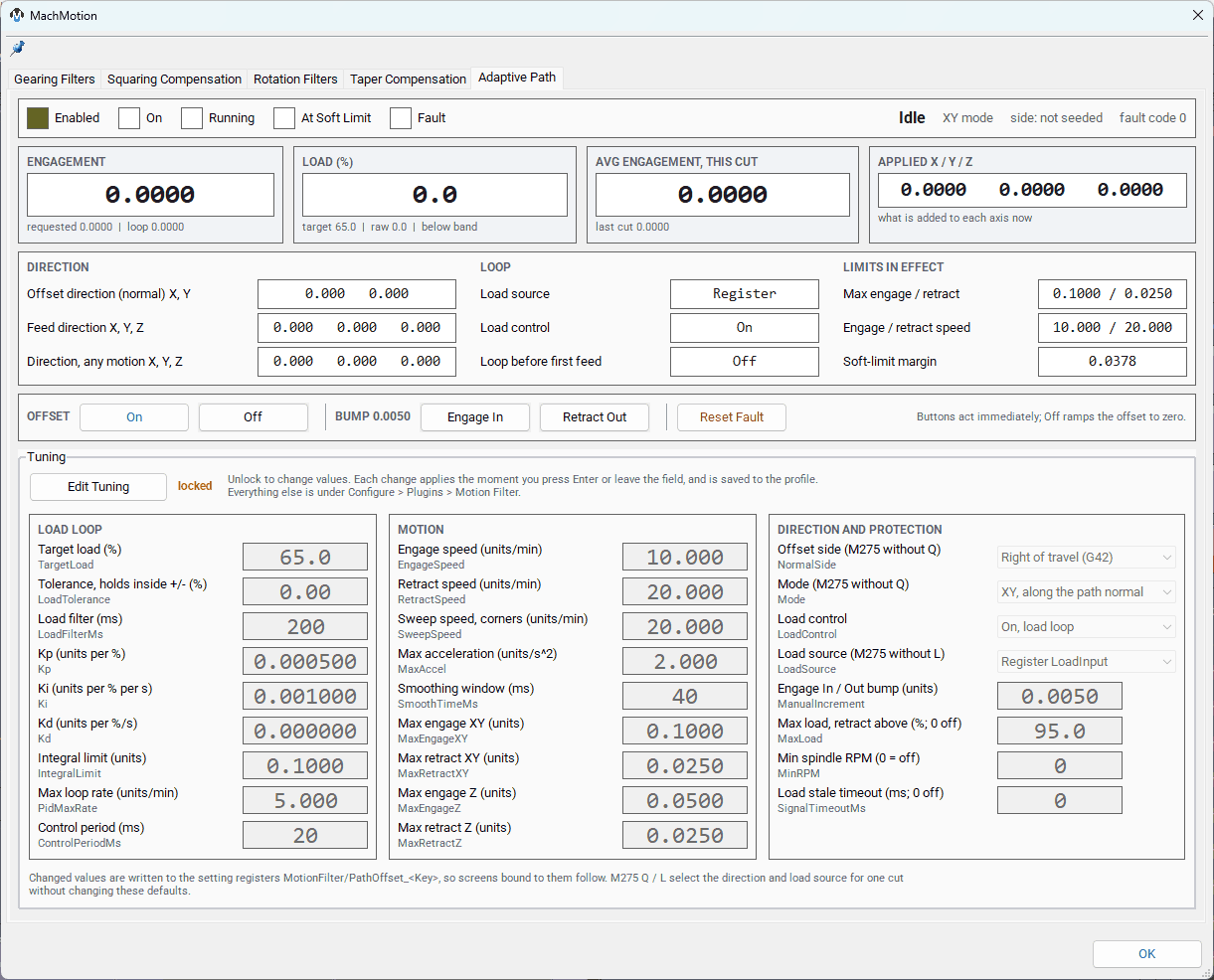
The Motion Filter diagnostics window has an Adaptive Path page for the feature. A status strip shows the LEDs and the state in words (state, XY or Z mode, which side of travel, fault code). Four tiles show the numbers an operator watches: the engagement (with the requested and loop values), the load against its target and tolerance band, the average engagement of this cut and the last cut, and what is applied to X, Y and Z. Below them are the offset and travel directions, the loop settings in effect (load source, load control) and the limits in effect, then the On, Off, Engage In, Retract Out and Reset Fault buttons. Below that are the tunable settings in three columns (load loop; motion; direction and protection, including the default side, mode and load source used when M275 gives no Q or L word). They are locked until Edit Tuning is pressed, so a stray click cannot change a running loop; once unlocked, each edit applies the moment you press Enter or leave the field and is saved to the profile. Press Lock Tuning to lock the fields again.
Protection and Lifecycle
Load above MaxLoad, spindle below MinRPM, or a stale or invalid load reading retracts the offset to zero and latches a fault (optionally with a feed hold). A cycle stop zeroes the loop offset and ends the cut. A tool change holds the offset at zero until the next feed move. Machine disable freezes the applied offset; enable adopts it without moving. Rapids and jogs while on hold the offset. The feature refuses to turn on in lathe mode or with unhomed axes. The soft-limit clamp keeps the programmed position plus the offset inside the axis soft limits by the offset's own stopping distance.
Gearing
Overview
Gearing slaves one axis motor to another at a fixed ratio. It is used where two axes must move together mechanically — for example a gantry or a linked rotary. The slave’s planner position is unaffected; only the motor output receives the extra, ratioed motion.
| M-code | Purpose |
| M34 | Gear a slave to a master. Q = master axis, S = slave axis, R = ratio (default 1). |
| M35 | Un-gear a slave from a master. Q = master axis, S = slave axis. |
(Gear Y (slave) to X (master) at 1.5:1)
M34 Q0 S1 R1.5

(Un-gear Y from X)
M35 Q0 S1
Gearing can optionally enforce the slave’s soft limits, clamping (and optionally alarming) if the master would drive the slave past its travel. See MotionFilterModule.SetGearingSoftLimits.
Lua Module Reference
MotionFilterModule (loaded as mf in the screen and M-code environments) is the scripting interface. Every function that sends a command first checks that the plugin is enabled. Functions return (success, rc, response) where response is the plugin’s reply string ("OK" on success) unless noted otherwise.
General
| Function | Purpose |
IsMotionFilterPluginEnabled() |
Returns true if the plugin is enabled in the profile. |
SendCommand(command) |
Send a raw command string to the plugin API register. |
Gearing
| Function | Purpose |
GearAxis(master, slave, ratio) |
Gear the slave to the master at ratio (negative inverts). |
UngearAxis(master, slave) |
Remove gearing. |
IsGearingActive(master, slave) |
True while the pair is geared. |
SetGearingSoftLimits(slave, enable, ramp_distance, alarm) |
Configure slave soft-limit enforcement during gearing. |
GetGearingSoftLimits(slave) |
Query the current soft-limit setting. |
IsGearingAtSoftLimit(slave) |
True while the slave is being clamped at a soft limit. |
Axis Override
| Function | Purpose |
OverrideAxis(primary, secondary) |
Copy commanded motion of the secondary axis onto the primary. |
RemoveOverrideAxis(primary, secondary) |
Remove the override. |
IsAxisOverridden(primary, secondary) |
True while the override is active. |
VerifyAxisAtZero(axis_id, message) |
Pre-check used before applying / removing an override. |
Taper Compensation
| Function | Purpose |
SetTaperComp(slave, master, ratio, pivot_mach, track_part, ramp_percent, ramp_min_s) |
Engage or update taper comp. pivot_mach is machine coordinates; track_part makes the pivot follow the part on tool changes. |
RemoveTaperComp(slave) |
Ramp the correction to zero and disengage. Idempotent. |
GetTaperComp(slave) |
Read the feedback registers: returns a table { ratio, pivot, master, applied, state }. |
IsTaperCompActive(slave) |
True while the pair is engaged (ramping or active). |
WaitForTaperCompSettled(slave, timeout_ms) |
Block until the ramp settles (ACTIVE or OFF). Used by M256 / M257. |
The state value from GetTaperComp is: 0 = off, 1 = ramping in, 2 = active, 3 = ramping out.
Adaptive Path Offset
| Function | Purpose |
PathOffsetOn(initial_engage, target_load, direction, load_source) |
Turn on; all arguments optional (nil = settings). Direction 1 left / 2 right of travel (X/Y), 3 Z down / 4 Z up; load source 1 spindle, 2 register, 3 Z axis, 4 X/Y axes. |
PathOffsetOff() |
Ramp the offset to zero. |
PathOffsetWaitForZero(timeout_s) |
Block until the offset is off (after PathOffsetOff). |
PathOffsetEngageIn(distance) / PathOffsetRetractOut(distance) |
Immediate bump toward / away from the part (nil = ManualIncrement). |
PathOffsetSetTarget(pct) / PathOffsetSetSide(side) |
Change the target load / the side while on. |
PathOffsetGetAverageEngagement() |
Average achieved engagement of the last completed cut. |
PathOffsetGetAchieved() / PathOffsetIsOn() |
Current achieved offset / on state. |
PathOffsetSetParam(key, value) / PathOffsetGetSetting(key) |
Write / read a setting register (applies immediately, persisted). |
PathOffsetSetLoadInput(value) / PathOffsetGetLoadInput() |
External load feedback register (load source 2). |
PathOffsetResetFault() / PathOffsetReloadSettings() / PathOffsetQuery() |
Clear a fault / reload motor limits / read a status table. |
Squaring
| Function | Purpose |
SetSquaringAngle(angled_axis, following_axis, degrees) |
Set the out-of-square angle and the axis that compensates. |
LockSquaring(enable, adjust_units) |
Activate squaring (all angles must be set first). |
UnlockSquaring() |
Release squaring. |
Logging
| Function | Purpose |
EnableLogging(enable) / DisableLogging() |
Turn position logging on or off. |
LogAxis(axis) |
Enable detailed logging for one axis. |
QuickLog(axis) / QuickLogAll() |
Capture a brief position snapshot for one or all axes. |
Command Protocol
Scripts talk to the plugin by sending semicolon-delimited command strings to the MotionFilter/API register via mc.mcRegSendCommand() (wrapped by MotionFilterModule.SendCommand). The command surface:
| Command string | Lua wrapper |
lock axis gearing;{slave};{master};{ratio} |
GearAxis |
unlock axis gearing;{slave};{master} |
UngearAxis |
set gearing soft limits;{slave};{0|1} |
SetGearingSoftLimits |
override axis;{primary};{secondary} |
OverrideAxis |
remove override axis;{primary};{secondary} |
RemoveOverrideAxis |
taper comp;{slave};{master};{ratio};{pivot};{track};{ramp%};{ramp_min_s} |
SetTaperComp |
remove taper comp;{slave} |
RemoveTaperComp |
get taper comp;{slave} |
GetTaperComp (reads registers) |
set squaring angle;{angled};{following};{degrees} |
SetSquaringAngle |
lock squaring;{enable};{adjust_units} / unlock squaring |
LockSquaring / UnlockSquaring |
enable logging;{0|1} / disable logging |
EnableLogging / DisableLogging |
open diagnostics / close diagnostics |
— |
path offset on;{initial_engage};{target_pct};{side} |
PathOffsetOn |
path offset off |
PathOffsetOff |
path offset engage in;{distance} / path offset retract out;{distance} |
PathOffsetEngageIn / PathOffsetRetractOut |
path offset set target;{pct} / path offset set side;{1|2} |
PathOffsetSetTarget / PathOffsetSetSide |
path offset set param;{key};{value} / path offset reload settings |
PathOffsetSetParam / PathOffsetReloadSettings |
path offset reset fault / path offset query |
PathOffsetResetFault / PathOffsetQuery |
Diagnostics Window
The plugin’s diagnostics window (opened with the open diagnostics command) has a tab per filter family — Gearing Filters, Squaring Compensation, Rotation Filters, and Taper Comp. Each shows live per-axis state. The Taper Comp tab lists one row per slave axis with an Active LED and read-only Ratio, Pivot, and Applied columns, so you can confirm the correction the plugin is actually applying independently of the screen dialog.
If the adjust dialog and the diagnostics window disagree on the applied correction, the diagnostics window is authoritative — it reads the plugin’s live state directly.
Components
| File | Purpose |
Plugins/MotionFilter/MotionFilter.cpp |
Plugin entry point, message handling, command dispatch, push/pop orchestration. |
Plugins/MotionFilter/RatioFilter.cpp |
Gearing filter implementation. |
Plugins/MotionFilter/AxisOverride.cpp |
Axis override filter implementation. |
Plugins/MotionFilter/TaperComp.cpp |
Taper compensation filter implementation. |
Modules/MotionFilterModule.lua |
Lua scripting interface (mf). |
Modules/CommonMCodeModule.lua |
Hosts _m34, _m35, _m256, _m257 implementations. |
Profiles/<profile>/Macros/m256.mcs, m257.mcs |
G-code macro wrappers for taper comp. |
Profiles/<profile>/Settings/Standard/Common/settings.TaperComp.csv |
Taper Comp OEM parameter definitions. |