M31 Knee Mill Installation
![]()
This installation manual shows you how to install your M31 Knee Mill system.

Mount Back Panel
Remove old components
- Remove everything in the electrical enclosure besides the original transformer.
- Measure the size of your current electrical enclosure. The new back panel is 21" x 21". If your electrical enclosure is too small you will also have to remove the original door switch.
- Remove the old cables running to the motors.
Mount the new panel
| MachPro M31 Knee Mill |
|---|
|
|
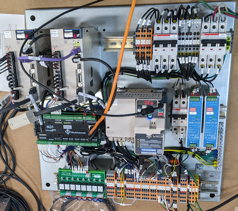
- Drill holes into the old back panel.
- Mount the new panel onto the original back panel.
- Mount the brake resistor to the wall of the electrical enclosure but close enough so the cables will reach the VFD.

Mount Control
See the 2000 Series Mounting Arm Manual to mount the arm and control.
Connect Control and Power
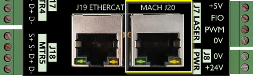
Connect Cables to the Control
- Remove round, rubber plug from the back of the control. Run conduit from the control to the back panel.

- Connect ethernet cables, power connector cable, and E-stop cables into the control as shown below.
- From the back of the control, connect the J2 Motion port to the J20 Mach port on the M31 motion controller
-
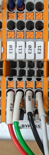
Connect the E-Stop wires (E10, E11, E20, E21) from the back of the control to the terminal strips on the bottom of the panel.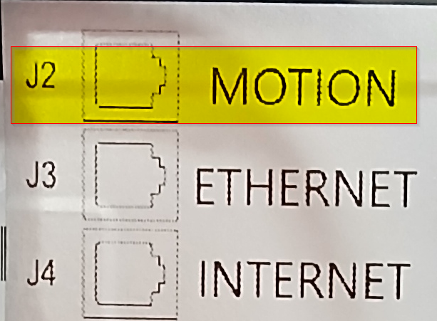
Connect the "Internet" cable to your local network if you do not plan to use the built in WiFi. Internet is not necessary to run the control. However, help from our support team requires remote access to the control.
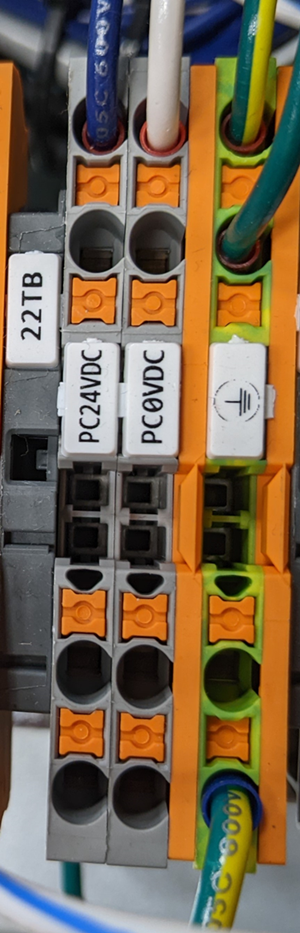
- Connect the HMI control Power Connector cable to PC 24V, PC 0V and GND blocks.


Wire Incoming Power
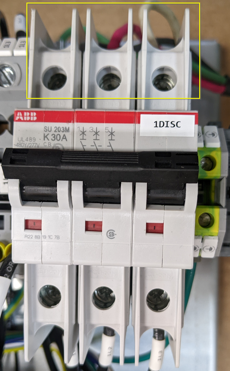
- Wire incoming power to the back panel at the main disconnect breaker: 1DISC. Be sure you are bringing in the 208-240VAC. The back panel can run on single phase or 3 phase.
- Note the max spindle motor power limitations:
- 5hp spindle motor with three phase power
- 3hp spindle motor with single phase power
- Note the max spindle motor power limitations:
- Optional Connect the transformer. Start by identifying the primary and secondary side of the transformer. The transformer will be fed with 240VAC and we need 120VAC output. If the transformer doesn't have clear markings and your machine doesn't have a schematic, you may have to google the transformer part number to figure out how to wire it.
- For example, in this transformer you will connect 240VAC to H1 and H4 and you will get your 120VAC power from X1 and X2.

- For example, in this transformer you will connect 240VAC to H1 and H4 and you will get your 120VAC power from X1 and X2.
- Connect primary side of the transformer to 240VAC from the two 4FU fuses shown below. Then connect the secondary side to 5CB and terminal 502.
- Make sure to ground the secondary side of the transformer. In the example above, you would ground X2.

- Make sure to ground the secondary side of the transformer. In the example above, you would ground X2.


Mount Motors
Mount the motors to the machine using the motor mounting plates provided. If possible, take a look at the gears and write down the number of teeth on the motor gear and the ball screw gear. If you write down the gear ratio specifications, ball screw pitch, etc. now, it will make calibration much faster later.

Run Cables
Route Motor Cables
Run the motor cables (Encoder and power) from the motors to the back panel. If the machine was equipped with CNC components before the retrofit the cables can usually follow the path of the old motor cables.
Take care when running the cables to keep them away from pinch points and sharp edges. The cables are protected by robust insulation but repeated wear and tear will cause damage and eventual failure. If the cables must run over a possible wear point, use some form of loom for additional protection. Keep in mind the motion of the machine and possible cable snag points while the machine is moving.
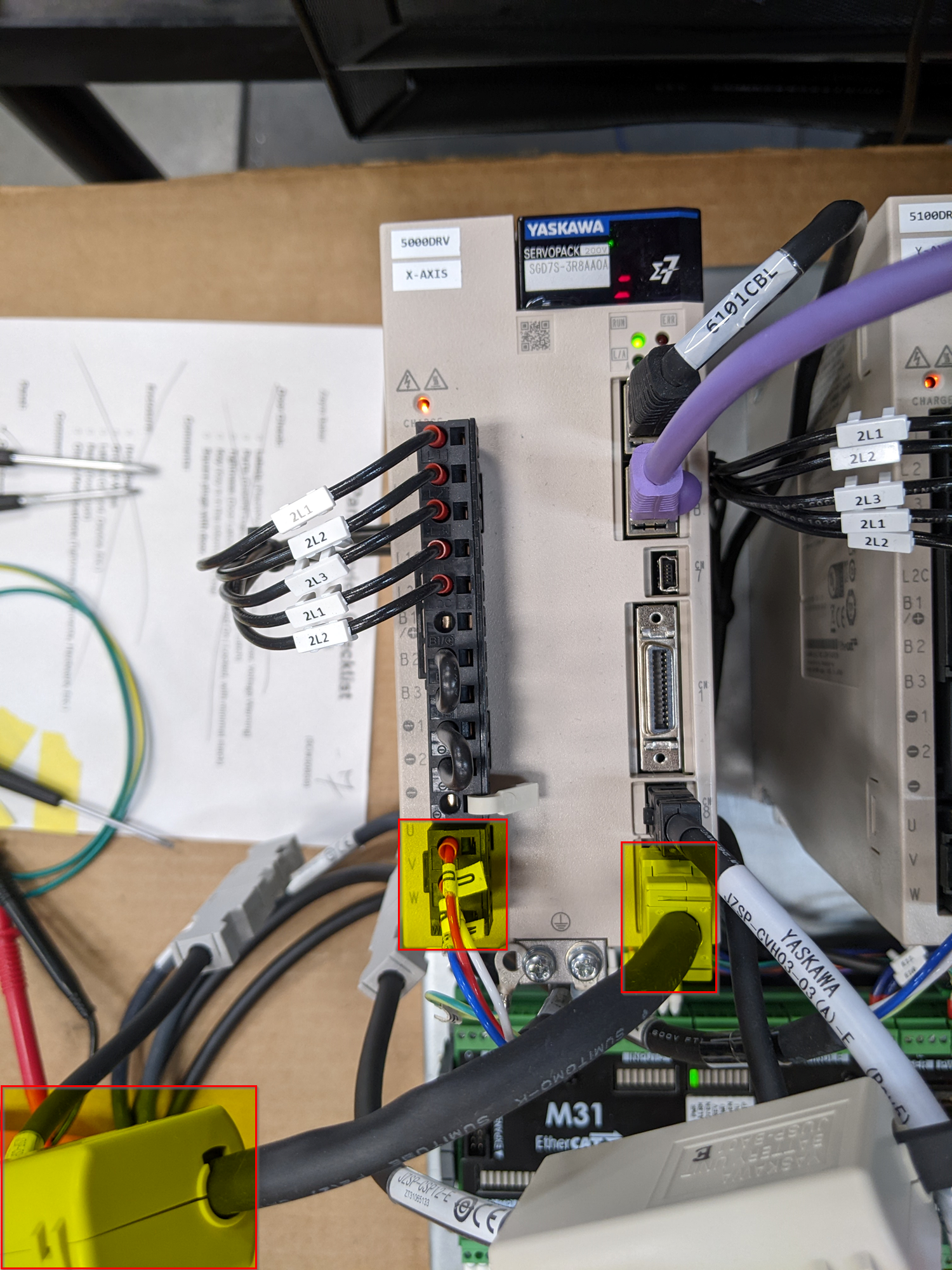
Connect Cables to Drives
Be very careful to keep the power and encoder cables together for each axis
The motor power cables have standard connectors on the motor side, and flying leads labeled U, V, and W to connect to the drives.
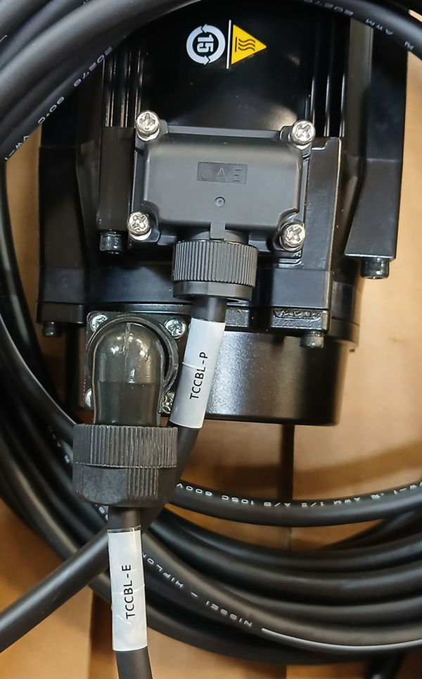
The encoder cables have a short battery pack cable extension to power the absolute encoder feature. Attach that short cable directly to the CN2 port on the Yaskawa drive, then attach the long encoder cable to run to the motor.
Wire Spindle Motor
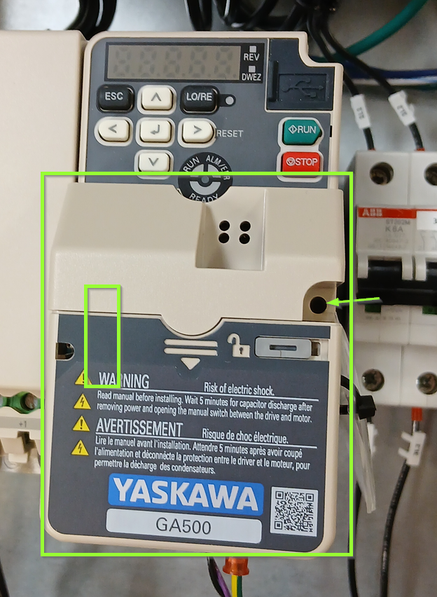
Yaskawa GA500
- Loosen screw and remove the EtherCat communication module. There is an electrical connector on the left side that will provide a little resistance as you lift the module off.


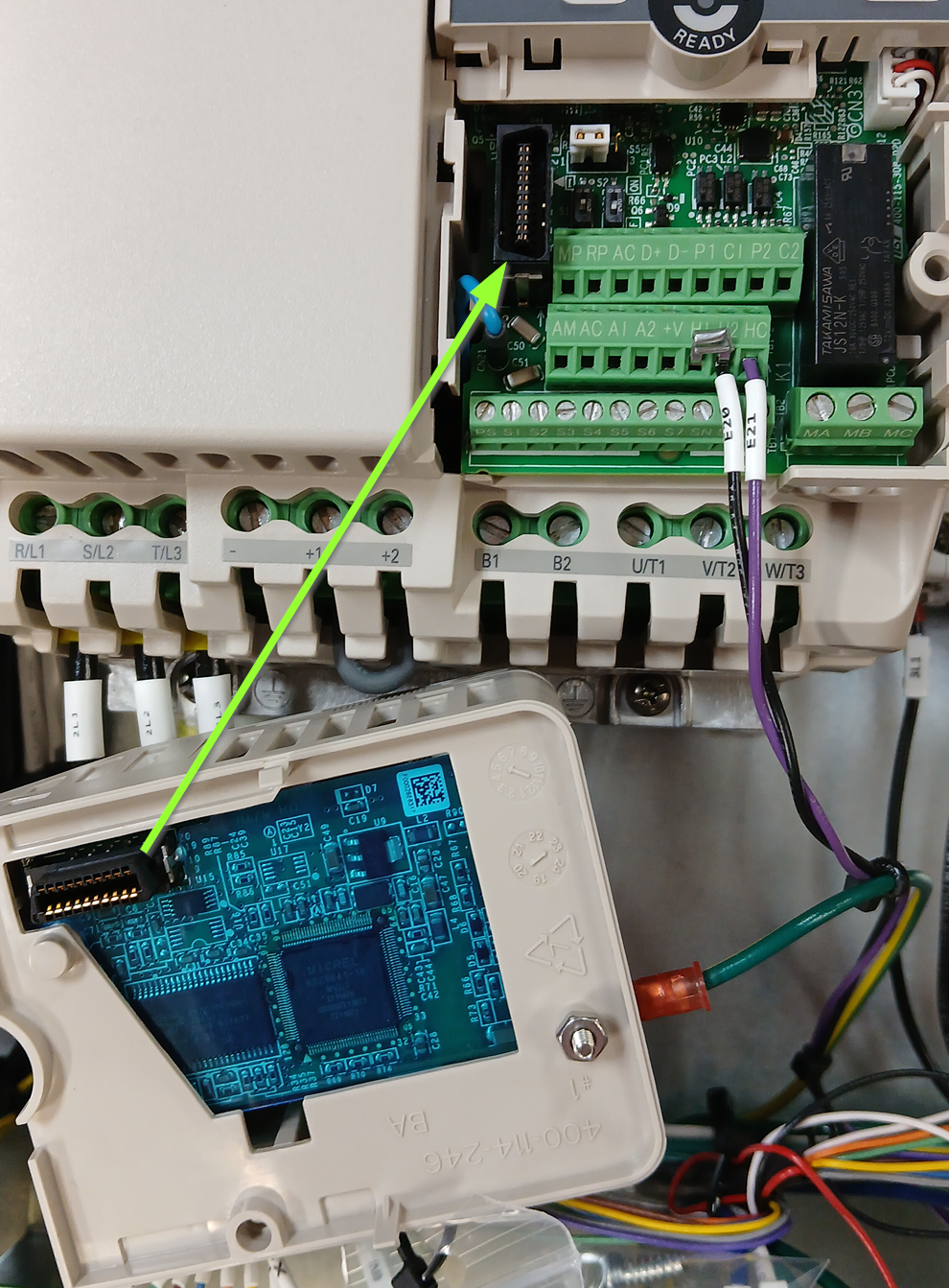
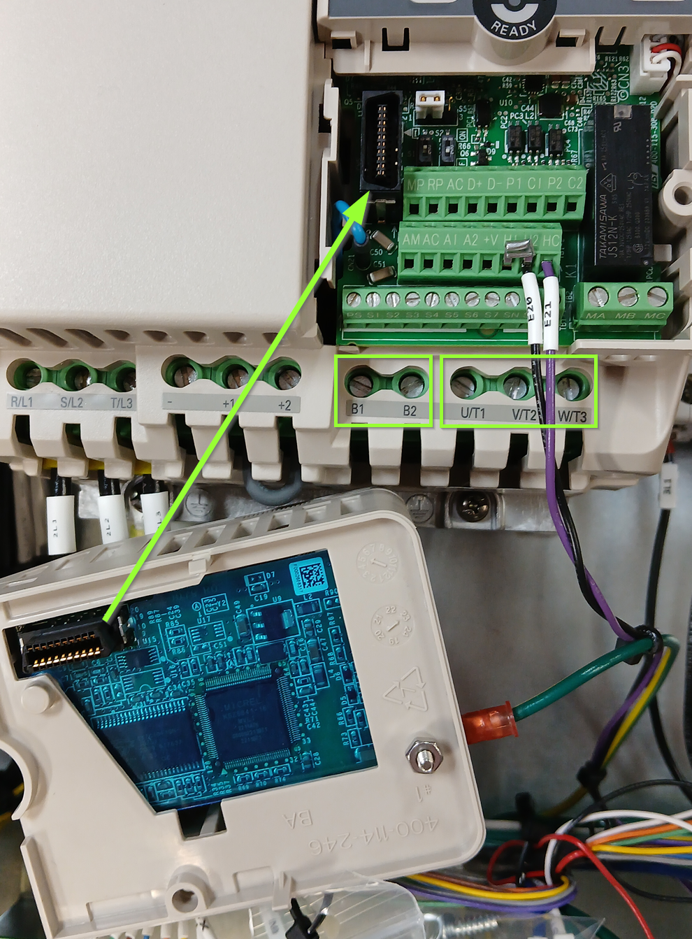
- Connect your spindle motor to the terminals labeled U/T1,V/T2, and W/T3, and connect your brake resistor to B1 and B2.

- Carefully line up the connector and reinstall the EtherCat communication module on the VFD.
Wire Inputs and Outputs
Wire any inputs and outputs as shown in the diagrams below.
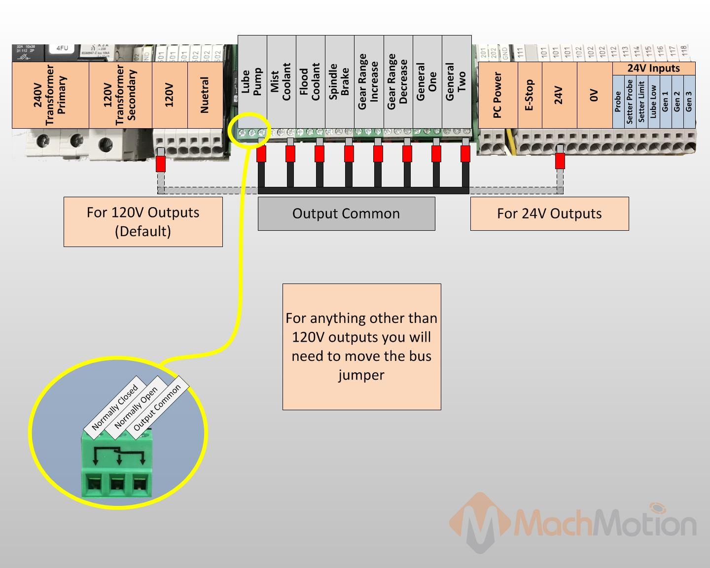
Output Commons
Please note, the output common comes pre-jumpered to the 120v circuit to the left of output wiring block as shown below. Verify the voltage of each output destination before wiring. If any of your outputs run on 24VDC, make sure the output common for that output is jumpered to 24V.
Wiring Lube System

Wiring Coolant System
For a contactor with 120VAC coil, wire it as shown.

Note: The contactor shown above is not included. Use the original contactor on your machine.
Coolant Pump Power
You can power up to a 0.5 hp 3 phase coolant motor. To run a 3 phase motor, the back panel will have to be powered with 3 phase. Run 3 wires from 2L1, 2L2, and 2L3 on the top of the back panel to the contacts on on your contactor.

Wiring Spindle Brake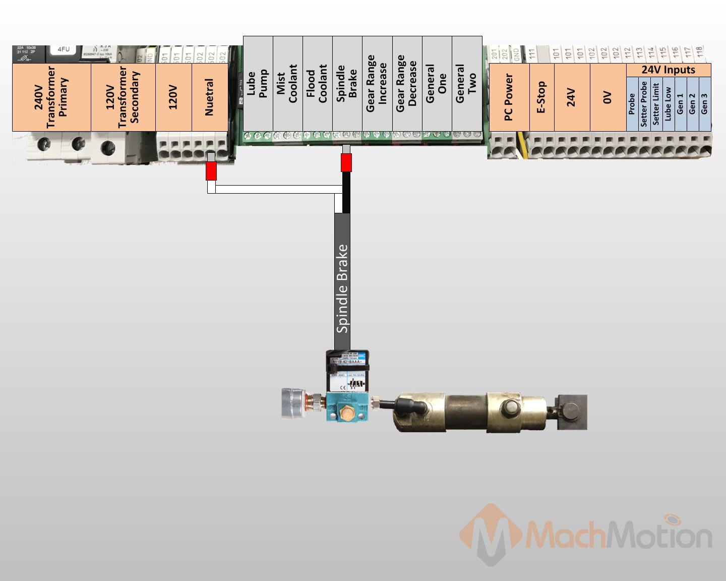
Wiring Tool Setter

Wiring Probe

Power System Up
Carefully inspect incoming power to make sure it is within range for your system. Most systems use 208-240 VAC.
We recommend utilizing a Multimeter to check incoming power. If using 3 Phase, check all 3 phases.
- Turn the door switch on.
- Check the transformer is outputting the correct voltage as well.
- Run motion on the machine
- Lower the jog rate using the knob on the control

- Carefully jog each axis. Confirm that they are traveling in the right direction. You can verify your axis direction using this diagram. It's based off of the right hand rule. Make sure to reference the TOOL and not the table movement.
- Lower the jog rate using the knob on the control

-
- If a motor is traveling in the wrong direction it can be easily reversed in the Mach4 software. First you will need to make sure your control is Disabled. Navigate to the top left of the screen and click Configure>Control and then click on the Motors. Select the problem motor and check the Reverse check box.
- Test inputs and outputs
The best way to do this is use the buttons already setup for the intended function. For example, "Coolant" has a hard button on the control. You can also toggle signals manually by going to the Service tab, then Machine I/O. Double clicking on a signal will change its state. Double click again to change it back.

Configure Software
There are two options for setting up units and soft limits. Typically, the easiest way is to use the MachMotion Knee Mill Setup Wizard. For more complex configurations, or customization, please refer to the M31 Motion Control Setup Manual
Knee Mill Setup Wizard
Select the Kneemill Setup Wizard from the Configure drop down on the main menu. This will guide you through an initial setup process that will allow you to set axis unit calibration, soft limits, and spindle calibration. You can also go through each step manually by following the information on completing the set up process for Units Calibration and Soft Limits outlined below.

Upon selecting the Kneemill Setup Wizard, you will be presented with a selection of configuration options. Yellow triangles indicate which features have not been completed yet, and green check marks correspond to previously completed items. It is suggested to do the items in the following order:
- Units
- Softlimits
- Spindle Calibration
- Backlash

Units Calibration
To set the units for each axis, the pitch of the ballscrew, the number of teeth on the ballscrew pulley, and the number of teeth on the motor pulley must be known. An advanced option is available for other systems of motion or if the data is not known.
The wizard will go through each axis individually in order (X, Y, Z). For each axis, you must enter the three pieces of data. Every time you change the data, the new units will be calculated and applied to the axis. To verify the units, a 1" dial indicator can be used. The wizard supplies options to move the axis back and forth distances up to an inch. Otherwise, verification can be done by manually jogging or commanding MDI motion.

Soft limits
It is suggested to go through this part with the machine disabled and to use the handwheels to move the machine. It is possible to move the machine with the jog functionality or pendant if the speed is turned down and caution is used.
Use extreme caution when jogging the machine. Until the soft limits are set it is possible to run an axis to its hard limit.
The softlimits wizard will go through the three axes in order (X, Y, Z) and ask you to move the machine first to maximum travel and then to minimum travel. The positions should be within machine physical limits and within any limit switches on the machine, but should encompass most of the usable machine.

For each position, you will either need to select Set Softlimit or Skip in order to proceed. As you move through the wizard, the image will change to help you visualize the correct positions. When you set the maximum softlimits for each machine, the control will set your Home position to the same place, unless the machine has previously been homed.
For reference, while facing the machine, X maximum travel is with the table all the way to the left and the spindle nose all the way to the right of the table. Y maximum travel is with the table as close to the operator as it can go and the spindle nose near the far edge of the table.
After exiting the wizard, limits will be activated. It is now possible to enable the machine and jog the axes into their limits. When the limit is reached, the machine will cease moving in that direction. It is a good idea to turn down the jog rate and test the limits at this point.
Use extreme caution while testing limits in the event that an axis was accidentally skipped or set at an incorrect position.
Backlash
Backlash is caused by the gaps between moving parts such as gears and ballscrews. It is the amount of movement one component can make in one direction without causing motion in the next connected part. Most mechanical systems have some backlash - even when new. If the mechanics are too tight, binding and excessive wear will result. As the gears and ballscrews wear, the backlash will increase, and accuracy will decrease. Ongoing testing and maintenance of your mechanical system is required to minimize backlash.
The M31 provides software backlash compensation as a short-term solution for small, stable amounts of backlash. To calculate the backlash of an axis use How To Test For Backlash
In the case that you have less then .0005" of backlash, this step may be skipped. Backlash compensation will not completely compensate for all mechanical deficiencies.
Be sure to start this wizard with each axis near the middle of travel. The machine needs minimum of 1" of travel in all directions for this wizard to succeed.
The wizard supplies buttons for moving the machine positive and negative 1 inch, input for the amount of error, and an indication of direction of error.

For each axis, move the axis negative and then attach a dial indicator and zero it. Then move the axis positive once. Input the error from the indicator and select the direction of error. Then select Calculate & Apply. Verify the backlash by repeating the process until the machine is consistent.
VFD Setup
Your Variable Frequency Drive will need to be configured for your spindle motor. Please refer to the manufacture's documentation for both the VFD and spindle motor. The VFD will have a way to view and change parameters through the face of the drive, and there may also be software that you can run and connect to the VFD through a USB cable.
You can find out what parameters need to be changed by looking at the info on your spindle motor name plate. Check and change any of the values that need it (Number of poles, wattage, amperage, etc.) to make sure your spindle runs at peak performance.

Spindle Calibration
The spindle calibration wizard requires you to read the specifications from the spindle and insert them into the wizard. The information needed is the maximum RPM for low gear, the maximum RPM for high gear, and the amps for full load. These should be input and then Save selected.
The spindle can be tested by inputting a spindle speed on the screen and then pressing the Spindle FWD or Spindle REV buttons on the panel. If the spindle is turning the incorrect direction, the Reverse spindle direction check in the wizard can be toggled. Be sure to select Save.

If you want to calibrate your spindle with a tachometer, please see the VFD - Spindle Calibration documentation.
These instructions apply to all VFDs where the spindle is controlled through the Mach4 Control Spindle tab
Why calibrate your spindle?
Does your CNC control need it? Yes - it needs to be accurate enough to meet your needs.
- The rated speeds and feeds for your tools and materials should perform as expected.
- You should have comparable performance across all your machines when running the same spindle speed.
- Accurate spindle calibration enables you to make cleaner and more accurate cuts – improving the quality of your final product.
- Scheduled preventative maintenance should include verification of the accuracy of the system, including the spindle speeds.
This documentation focuses on knee mills as a common example and is adaptable to other machines.
Spindle control methods
The specific spindle control method is configured during the installation. This document assumes that the spindle motor ID plate parameters for your VFD have been entered into the software, and the VFD and motor are operating correctly. If you are unsure, verify the control method is configured using the links below. This calibration step is the last part of the spindle and VFD setup.
- Analog 0-10v from the Apollo III is managed through the face of the drive with Yaskawa Drive Wizard software. The wiring configuration is documented here in the 2000 Series Apollo III Operating Manual.
- Ethercat VFDs are configured through RapidPath. Note that we often build panels with RapidPath motion control and Modbus VFD control. Verify that the VFD is part of the RapidPath system. If not, refer to the Modbus section below, or the Analog 0-10v section above. RapidPath sends a speed command to the VFD – often an RPM command. If that implementation is correct, you should have accurate spindle speeds. Small calibration adjustments can be made in the Mach configuration spindle tab, and that is documented below. If your spindle speeds are significantly off, you need to contact MachMotion support for assistance.
- Modbus VFD configuration is described here: Yaskawa V1000 / A1000 / GA500 / GA800 TCP Modbus Communication Setup
Definitions
Machines often have both gears and speed controls.
The control needs to know which physical gear is engaged to control the spindle motor for the correct speed. If you use multiple gears on your machine, there will be gear change buttons on the screen, and you can also use M-code commands to change gears. When you command a gear change, the software will prompt you to make the physical gear change, then it will change the software parameters to match.
The speed control is a set of variable diameter pulleys that provide a variable speed within each gear. We often set this to the maximum RPM. Then we use the VFD to provide the full speed range within each gear.
Set MaxRPM values for each gear
Note: The MaxRPM is where you adjust the maximum tool RPM. To calibrate the TSpeed adjust the feedback ratios. You can overspeed a motor using these instructions.
If you do not have a tachometer
Pull down Configure | Control | Spindle tab
If your machine only has one range (no pulleys or gears), then enter the minimum and maximum RPM for the spindle in the Range 1 row.

If you have a tachometer
Use the steps below to set the MaxRPM:
- Set the spindle override knob on the operator control panel to 100%
- Temporarily set all MaxRPM values to twice the labeled RPM on the speed control. This is not to destroy your machine. For calibration purposes this forces the VFD to the maximum hertz output - therefore the maximum tool RPM. We use that to calibrate accurate tool RPM for normal production.
- Verify that the VFD is sending the maximum Hz to the spindle (see next section)
- Run your machine in each gear range with the temporary MaxRPM values you used above. Verify that the VFD is putting out maximum Hz. Record the actual MaxRPM values from the tachometer for each gear range.
- Enter the actual MaxRPM values that the tachometer reported in the spindle tab.

If it is not safe to run this spindle at its maximum RPM, please call MachMotion for assistance with calibration.
Verify that the VFD is sending maximum speed commands to the spindle
You need to know that the VFD is telling the spindle motor to run at full speed. Assuming the motor is configured to run at 60 Hz, then if the VFD is sending 60 Hz, the motor is running at full speed. You just entered the MaxRPM values into the spindle config. Set your machine for one of the gears and run the spindle at the MaxRPM. You can check the VFD output two ways, and both are equally accurate:
|
|
|
|
With the enclosure door open, check the LED on the VFD. This VFD is running at P44.59% of 60 Hz = 26.754 Hz. The "P" prefix on the number indicates the number is a percentage.
|
Open a web browser and enter this IP address in the search bar 192.168.208.90. It will open a welcome page for the VFD with two buttons at the bottom. Click the Monitor button and look for the Output Frequency line. This is the same machine running at the same time, and it also reports 44.59% = 26.754 Hz. |


Adjust feedback ratios for TSpeed
The formula is MaxRPM / Maximum Motor RPM = feedback ratio
Pull down Configure | Control | Spindle tab

Check the ID plate on the spindle motor for RPM values. In this image we are running at 60 hertz; so we use the second value: 1735

MaxRPM from tachometer / Maximum Motor RPM = feedback ratio
4485 / 1735 = 2.5850144092219020172910662824207
You can paste the the full value into the spindle FeedBack Ratio field for this range, or just 2.58501
Note: the feedback ratio only adjusts the value in the TSpeed field. It does not have any effect on the actual RPM of the spindle. If the spindle speed reported by a tach does not match commanded speed, then go here: Set MaxRPM values for each gear
Operating the spindle
Use M-Codes to operate your spindle during production: M3, M4, and M5 (relevant portion of the G-Code and M-Code Reference)
You can manually control the spindle with the buttons on your operator panel.
The gear ranges can be changed from the control by using M40-M45. The macros can be used to just change ranges or they can be used to automatically change gears on the machine. To shift the machine range 0, run M40. M41 is range 1, M42 is range 2, and so on. You will be prompted to change the gear manually. M40 P# can also be used where # is the gear range to use.
Special situations
Overspeed a spindle motor
If you want to command your spindle motor or grinding wheel to go faster than the base frequency, command the spindle to go max RPM and use a tachometer to measure the speed. Then use the following formula to calculate your new Max Output Frequency (Hb105):
Desired Max RPM * Current Max Frequency / Current Max RPM = New Max Frequency
For example, if your Current Max Frequency is 60 and you measure the spindle runs 1030 RPM but you actually want it to go 1515 RPM, calculate your new Max Frequency as follows:
1515 * 60 / 1030=88 Hz.
Make sure to recalibrate your RPM feedback and your spindle speed as shown below.
Set a spindle to always run at maximum RPM
In some cases, a machine was originally configured to run the spindle motor at full speed, and the gears and speed controls are used to bring the RPM down to the required value. A motor running this way will always generate its maximum torque, which is very helpful when using large tools.
Pull down Configure | Control | Spindle tab

Set your MinRPM and MaxRPM for each gear to the same value.
Set your Max Spindle Motor RPM to the rated value listed on the spindle motor plate.
Leave the FeedBack Ratio values alone as they are no longer meaningful.
The spindle section of you screen can now be ignored. You will adjust your spindle speed entirely through the gears and speed control.

The rest of the spindle configuration above is not needed when it is configured to run maximum RPM.
Automatic Gear Shifter (Siemens PLC)
Spindle gear range 19 is used for the automatic gear shifter.
Default MachMotion Parameters

Note: Make sure to not have outputs mapped both in Mach and in the PLC.

Auxiliary Spindle MaxRPM
If your VFD is enabled as an Auxiliary spindle (under MachMotion Parameters), set the Auxiliary Control Max RPM to the max RPM of the tool or table. Use this value both in the VFD configuration, and in the sub spindle configuration. Also see this section on sub spindle configuration

Manual Setup
Units Calibration
Before the machine is homed or any further setup is completed we must calculate our steps per/unit and calibrate the motors accordingly. There is both an automatic process and a manual process: 2.4 Axis Calibration
Homing
With the motor units calibrated, we can now set the machine zero and set up the software limits.
Machine zero is used by the control for all movement calculations, but you will not typically use it directly. Your RPKM system has absolute encoders that maintain the position of each axis even when the machine is powered down. We will set the machine zero here once and you will not need to home your mill when you start it up.

- Go to your service tab. Turn off soft limits, enable and ensure that your axis labels are flashing red and yellow. If not, please call MachMotion for assistance de-referencing your axes.

- Carefully jog X to the most negative location that you want to use (the soft limit location), and then jog positive approximately one inch, where the X machine zero will be set.
- Repeat that process for the Y axis.
- Carefully jog Z up to the most highest location that you want to use (the soft limit location), and then jog down approximately one inch, where the Z machine zero will be set.
- Navigate to the Service Tab and click Home All. This sets the machine zero for all axes. If the Home All button is not active, please call MachMotion and we will help you de-reference all axes so that you can set your machine zero.

Soft Limits
Next we need to set up the soft limits to prevent crashes. On the upper left hand side of the screen pull down Configure and then Config Soft Limits.
Follow the prompts listed. Soft limit set up can be done on all axes at the same time, or one axis at a time. Continue until all axes are complete. Carefully test each axis to make sure that it will not go past the position you set for its soft limit.
Backlash
Backlash is caused by the gaps between moving parts such as gears and ballscrews. It is the amount of movement one component can make in one direction without causing motion in the next connected part. Most mechanical systems have some backlash - even when new. If the mechanics are too tight, binding will cause excessive wear. As the gears and ballscrews wear normally, the backlash will increase, and accuracy will decrease. Ongoing testing and maintenance of your mechanical system is required to minimize backlash.
The M31 provides software backlash compensation as a short-term solution for small, stable amounts of backlash. To calculate the backlash of an axis use How To Test For Backlash.
To manually adjust the software compensation for backlash, use these instructions: Backlash Repair and Compensation. Backlash compensation can not completely compensate for all mechanical backlash.
In the case that you have less then .0005" of backlash, this step may be skipped.
Lubrication Pump
Your kit is pre-configured with a relay to control the Lube Pump, as seen above. You can change the frequency and duration for the pump in the MachMotion parameters.
Pull down the Configure menu in the upper left corner of the screen, select Plugins -> MachMotion
Search for "Lube"
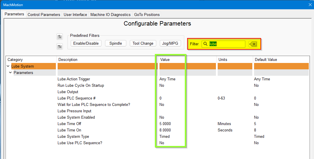
Adjust the values according to your machine's needs. Note that lube pumps vary widely in their output. Start conservatively and increase the values to achieve proper lubrication.
Additional Documentation
If you are just setting up your machine and getting used to the 2000 series control, check out these other manuals to learn how to use the control PC, operator panel and Mach4 Software.
For more info on the Control and Operator Panel, check out the "2000 Series HMI" (Human-Machine Interface) manual.
For information about Mach4 Software Operation please see "2000 Series Mill / Router Operating Manual"
Warranty Information
MachMotion warranty policy is subject to change. Updated information is available at our website:
https://machmotion.com/warranty
The MachMotion Team
http://www.machmotion.com
14518 County Road 7240, Newburg, MO 65550
(573) 368-7399 • Fax (573) 341-2672