2000 Series RapidPath Configuration Manual
![]()
Introduction
RapidPath is MachMotion's EtherCAT motion controller solution. It has integrations for a range of Yaskawa EtherCAT servo drives, VFDs, the Titanio EverCNC stepper drive, and a subset of the Beckhoff I/O devices. It can be licensed for up to 64 motors. The control uses a Windows interface to a real time operating system where the EtherCAT master resides. The operating system is called Intime and the interface is called RapidSetup.
EtherCAT Network Basics
Communication
An EtherCAT network is comprised of a communication master and a series of network nodes. Each millisecond, a packet of information (known as a frame) is sent from the master to the network and a responding frame is received back. The frame from the master includes information for each node, such as commanded axis position and outputs. The frame the master receives back includes feedback position and input status, among many other things.

Limits of increasing the performance of Industrial Ethernet protocols - Scientific Figure on ResearchGate. Available from: https://www.researchgate.net/figure/EtherCAT-with-100-Mbps_fig4_4304922 [accessed 21 Jan, 2022]
Building a Network
An EtherCAT network is a sequence of devices called nodes. A node is added to the network by plugging an EtherCAT cable from the out port of one node to the in port of the next node. The in port of the first node is attached to the EtherCAT port on the back of the control. The out port of the last node will be empty and unconnected. This will create a chain of devices in order.
I/O couplers will have multiple node items on the network for each coupler. Only the couplers have in and out ports, but each I/O slice is a distinct node on the network. Some I/O slices that are all 0V connections are not part of the network. Other example of potential network nodes include servo drives and VFDs.
Regenerating a Network
When there are changes to the network topology due to nodes being added or removed, the communication on the network will be shut down and the system will have to regenerate. If the machine is running during this time, all systems will disable. The machine is unable to be enabled while the network is not operational.
If the network has had nodes added to it, the regeneration process will need no interaction from the operator. If the network has had nodes removed from it, the control will ask if the user wants to override the saved topology and use the new network. This may result in settings or I/O mappings being lost, as some devices are no longer on the network. Note that the network does not distinguish unique order of nodes on the network; if you swap the order of two servo drives, control settings will not move with the original devices and may create unexpected motion.

Configuration
Overview
All configuration must be done while the machine is disabled.
Axis Configuration
Connecting Axes
An axis is added to the network by plugging an EtherCAT cable from the out port of one node to the in port of the new servo node. Adding or removing items from the network will break the communication stream and cause the network to regenerate. While the network is regenerating, the machine cannot be enabled and config cannot be accessed.
Enabling Axes
This may already be setup on your system.
The motors are labeled starting at zero. The first motor is the first motor on the network and sequentially added from there. All motors must be enabled before they can be assigned to an axis. See the Servo Spindle section for using a servo as a spindle.

After motors are enabled, they can be assigned to axes. An axis must have one master motor and can support up to five slave motors.

The machine can now run motion, but units and direction have not yet been calibrated. Use extreme caution when moving the machine.
Motor Direction, Velocity, and Acceleration
Motor Direction
By default, the control will assume that moving an axis in the positive direction is done by turning it's motors in the positive direction. This can be changed to match the physical mechanics of the machine.
If you are slaving motors for a gantry axis, they very often must run in opposite directions in order to not twist the machine. Exceptions exist, always jog slowly and watch for gantry twisting when first testing motion.
Maximum Velocity and Acceleration
The maximum velocity and acceleration values are set on a per-motor basis. If an axis has multiple motors, it will use the slowest values of it's motors. All values are set in machine units. The graph of the motion profile will update as you change these values.
Calibrating Units
For the axes to move the correct distance, the counts per unit must be calibrated correctly. For best results, automatically calculate the units from machine data. However, unit calibration can be quite good with manual calibration, especially if done over greater distances.
Automatic Unit Calibration
Automatic unit calibration requires detailed knowledge of your machine mechanics.
| Drive | Motor | PnB02 | Pn20E* |
Pn20E* In Calibration Window |
Resolution in RapidPath Plugin | Resolution in Calibration Window |
| Sigma 5 | Sigma 5 | 8 | 1 | 1 | 1048576 |
131,072 |
| Sigma 5 | Sigma 7 | 8 | 16 | 1 | 1048576 | 131,072 |
| Sigma 7 | Sigma 5 - Only used for MachMotion versions older than 21583 (Needs Verification) | 128 | 1 | 1 | 16777216 | 131,072 |
| Sigma 7 | Sigma 5 - Used for current versions | 8 | 1 | 1 | 1048576 | 131,072 |
| Sigma 7 | Sigma 7 | 8 | 16 | 1 | 1048576 |
131,072 |
*Pn20E cannot be changed on Yaskawa EtherCat servo drives.
4. Press the Calculate button.
5. Press the Accept button to save the changes to the motors.
6. Repeat at step 2 for all axes.
7. Click OK and restart the software to save the changes.

Manual Unit Calibration
Manual unit calibration does not require any knowledge of the machine mechanics, but does require an accurate way to measure distance moved by an axis.

Manual Unit Adjustment
The units for individual motors can be manually adjusted in the control configuration on the motors tab. This is not recommended for normal calibration. If the units are manually adjusted here, also adjust them to match on the Auxiliary Positions tab. You do not need to enable anything on this page, but the counts per unit must be kept in sync.
Backlash
The RapidPath motion controller supports backlash compensation. Backlash compensation cannot fix all errors in the mechanics. It is better to fix the mechanics than hope that backlash compensation can make up for it.
- Calculate the backlash value.
- Move the axis to be measured to the center of the machine.
- Open MDI and type gcode to move the axis in the positive direction.
- Mount a dial indicator to the axis and zero it.
- Using MDI, move the axis a specific distance in the positive direction.
- Move the axis the same distance in the negative direction.
- The backlash value is the amount that the dial indicator is off from zero.
- On the menu bar, click Configure -> Control, then select the Motors tab.
- Select the motor that you need to change by selecting it from the list on the left side. Be careful not to disable it by clicking the checkbox.
- Enter a value that is slightly less than the measured Backlash value in machine units.
- Press Apply to save any changes and OK to close the configuration window.
- On the menu bar, click Configure -> Plugins -> RapidPath, then select the Drives tab.
- Select the motor that you need to change by selecting it from the list on the left side.
- Enter the desired Backlash Rate. The rate is a percentage of the motors maximum velocity and is how quickly the backlash will be compensated for when changing direction. A common value is 20%.
- Press Close to close the configuration window.

At this point, axes should have correct motion with accurate units and reasonable speeds and accelerations.
The machine has not been homed and limits have not been set up. Use caution while moving the machine.
Drive Parameters
Drive parameters are directly editable from the control software without any additional cables.
On this page, you can view and edit all parameters on the drive. Edited parameters will be highlighted in green. The parameters can be saved to a file or loaded from a previous save.
This file format is not compatible with parameter files from other software.

Homing
RapidPath supports a variety of homing methods. The exact methods available will depend on the capabilities of your drives.
Units must be set up and accurate before doing any homing operations.
If limit switches are to be used on your machine, it is recommended to set those up before homing. See Limit Switches.
Home Status
The home status of any axis can be seen on the main page. If an axis is not homed, the letter by it's position DRO will flash red and yellow. If an axis is homed, the letter will turn black. All motors on an axis must succeed at homing for an axis to report homed.

General Homing Sequence
Axes can be homed individually or all together in their defined order. Each axis will follow the same general sequence for homing.
- Each motor on the axis will complete it's homing action as configured. Each method of homing requires different configuration needs.
- The axis will wait for all motors to be done.
- Each motor on the axis will move to it's end position.
- The axis will wait for all motors to be done and then report homed.
General Homing Setup
All axes must know which direction to travel in order to find their home position, the speed at which to travel at, the offset from the marker to call their home position, and the order in which all axes home. Axes can also be homed individually if needed.
Regarding Home Speed %, the axis must be sufficiently slow to not overtravel past it's home switch.
The Home In Place option is not supported on RapidPath.

Selecting Homing Method
The motor specifics of the homing operation are configured in the RapidPath configuration window. When choosing homing options for slaved or gantry motors, use caution when configuring the homing sequence that the motors do not pull the axis out of shape.
Homing Method Options
The homing methods below detail how a motor will find it's home condition. The homing method is configured in the RapidPath configuration window.
Home to Current Position
Home to current position does not move the motor in any direction. It will call it's current location the home position. This method is most often used with absolute encoders as repeatability can be difficult. Often the machine will be scribed to show where the home position is in case of needing to home again (eg. encoder backup battery error).
Home to Index Pulse
Home to index pulse will create up to one motor revolution of motion. The mechanics of your machine will dictate how much physical motion this will create. This method is most often used with absolute encoders as repeatability can be difficult. Often the machine will be scribed to show where the home position is in case of needing to home again (eg. encoder backup battery error).
Home to Switch
Home to switch will move the axis in at the homing speed in the homing direction until it finds the home switch, then moves in the opposite direction until just off the home switch. The home switch can also be a limit switch. The home input must be mapped in the control configuration window to the appropriate input signal, which will be named Motor # Home, where # is the motor number. See Home Switches in the I/O Configuration section for more information about assigning the I/O point to the home signal. For master and slave motors, the signals can be mapped to the same I/O point or different I/O points.
The motor must be moving sufficiently slow to not overshoot the home input.
Home to Switch, then Index Pulse
Home to switch then index will function the same as Home to Switch, but after finding the home switch the motor will move in the opposite direction to find the index pulse. The location of the index pulse will be the home location. This method is most reliable for repeatedly finding the same home location each time.
Homing Modifiers
The following parameters can modify the homing sequence to change where the home position is relative to the triggered home position (i.e. switch or index pulse) or can create motion on the axis to change where the axis moves to compared to it's home position is.
The following parameters are in the RapidPath configuration window:
Available modifiers:
- Home Offset: shifts the home position of the motor from the detected position, in machine units. This is most often used for slave alignment between multiple motors.
- Is Home Offset Directional?: determines if the Home Offset parameter is intelligently applied based on motor polarity and home direction, or if the direction of the offset is already included. Selecting No will have the control choose the direction to apply the offset. By default this should be Yes.
- Home Backoff Speed: an absolute speed (machine units/minute) that the motor will use to back off of it's homing condition. Most commonly used in Home to Switch or Home to Switch, then Index Pulse.
- Home End: Move to Position: enables the motor moving to an absolute position after determining it's home position. Due to accelerations and offsets, many home routines do not end directly at the machine zero position. Enabling this parameter will allow the machine to move to a specified machine position after homing.
- Home End: Move to Position Speed: an absolute speed (machine units/minute) the motor will use when going to the specified home end position.
- Home End: Move to Position Target: the machine position the motor should move to after finding the home trigger and applying the home offsets.
The following parameters are in the control configuration window:
Available modifiers:
- Home Offset: moves the home position for all motors on the axis by the specified value in machine units.

Enable Absolute Encoders
Absolute encoders can be enabled per motor. They must be enabled on the motion controller level and in the drive parameters.
2. Select the motor that you need to change by selecting it from the list on the left side.
3. Set the Encoder Type parameter to Absolute.

Note: If you need to home again and it shows it's currently homed, set the encoder type to incremental and then set it back to absolute. This will allow you to home the machine.
4. Select the Drive Parameters tab and wait for the current parameters to be read from the drive.
5. Set the drive parameter appropriately for the encoder type.
The documentation for the Yaskawa EtherCAT Sigma7 drives states that Pn002.2 (Pn002.B2) should be set to 0. You may also need to set Pn002.1 if you have an external encoder.

It should look like this in the Rapidpath plugin:

6. Click Write Changes to send the parameters to the drive.
8. Select the drive you are setting up on the left side and press Reset Absolute Encoder.

9. Shut down Mach4 and then cycle power to the drive.
Absolute encoders should be enabled!
Reset Absolute Encoder Error
After pressing the button, cycle power on the drives to clear the error.
Homing with Absolute Encoders
Now your DROs should be flashing between yellow and red. This will allow the homing buttons to work.

Home the machine and it will use your default homing method - home to a limit switch, home to index, home in place, etc.

When you home, your absolute position in the drive will be updated with a new zero position. This position will not change unless you rehome, disconnect the encoder cable, disconnect the motor from the machine, or something mechanically slips on the machine.
Note: If you are homing to limits to setup your absolute encoder positions, it is recommended to have a limit switch on the master and slave axis. If you don't, you can set an offset in the software to offset your slave axis. Contact MachMotion for more information.
Absolute Scales
For absolute dual loop encoders, you can calculate your steps per unit by the scale pitch (10um) and the interpolation factor from the .mgf file.
Steps per Unit = 1/Pitch * Interpolation Factor / PNB02.
For example, a 10um scale with 12 bit interpolation factor has a steps per unit of 1/40.96um*25.4*2^12= 2540000 steps per inch.
For the standard Endat22 encoders, use 2540000 counts per one motor resolution in the Rapidpath plugin. PnB02 should be set to 1. Your steps per should be 2540000.
See Yaskawa Fully Closed Loop Control Control and contact MachMotion for more information on how to setup external encoders.
First Homing
Homing should now be completely set up. Home each axis individually to verify the configuration. Press the Home All button again to make sure everything works correctly.
If homing is incorrectly configured, the machine could crash. Be prepared to trigger Emergency Stop until configuration is verified.
If limit switches are to be used on your machine, it is recommended to set those up before homing. See Limit Switches.

Soft Limits
After the machine is homed, soft limits can be set up. These limits affect the motion planning so that the axes will not go outside of the designated area.
The soft limits of the machine are denoted on the toolpath by dashed lines. When a gcode file is loaded, if any part of the toolpath renders outside of the soft limits, check your file or fixture offsets.
While the home switch may be outside of soft limits, machine zero must be inside soft limits.
Soft limits must be contained to stay within any physical limit switches in order to be effective.
- Home the machine.
- Change the position DROs to Machine Coordinates. This is indicated by them being orange. Part coordinates (defined by G54) are shown in gray.
- For each axis, jog the machine to one extent of travel and record the machine coordinate at that point. You may need to disable soft limits on the service tab. The soft limits button is in the upper left corner.
- For each axis, jog the machine to the other extent of travel and record the machine coordinate at that point.
- On the menu bar, click Configure -> Control, then select the Homing/SoftLimits tab.
- Enable soft limits on the desired axes by checking the Soft Enable checkmark on their row.
- Enter the corresponding recorded positions for each axis into Soft Min and Soft Max.
- Soft Min must be less than Soft Max.
- Zero (0.0000) must be between Soft Min and Soft Max.
- Press Apply to save any changes and OK to close the configuration window.
- Verify soft limits are active.
- Go to Service -> Maintenance on the main page.
- The Soft Limits button should be green to indicate soft limits are active.
- Verify the soft limits by jogging the axes to the extents of the machine in all directions.


During the normal course of operation, soft limits will be active when the machine completes homing.
At this point, the machine is safe to move while soft limits are active.
I/O Configuration
Beckhoff I/O Naming Convention
All I/O points on the system are identified by their device and name. The device will indicate the physical component the I/O is a part of and the name will indicate which terminal on the device corresponds to the I/O point.
RapidPath has integrations to Beckhoff I/O couplers and slices. The couplers are the devices and the slice order and terminal form the name of the I/O point.
The devices are identified by their part name and their order on the network. The most common coupler used is the EK1100, so the first coupler on the network is EK1100.1. The second coupler is EK1100.2. Most systems will only have one coupler, but larger systems with multiple banks of I/O will have multiple couplers.
Each terminal attached to the coupler is identified by it's slice type, slice number, and terminal number.
- Slice types are two letter designations for analog or digital and input or output. An analog output slice will be a AO type and a digital input slice will be a DI type.
- Slice numbers are counted starting at one from the first slice.
- All of the input and output cards are numbered in series from left to right.
- The 0VDC and 24VDC slices are numbered in their own series from left to right.
- Terminal numbers are counted from one to eight, in a left to right, top to bottom pattern.


Here is how the IO labeling works. Each new IO device to the right will have an incremental slice number.

Wiring
Here is an example wiring schematic for an input card.

Here is an example wiring schematic for an output card.

Here is a basic diagram showing a 24VDC input switch.

Here is a basic diagram showing a 24VDC output relay.
(In process)
Assigning I/O to Input Signals
There are 64 general purpose inputs available for use. Inputs should also be mapped to the limit switch inputs and the home switch inputs if those are part of your machine.

Limit Switches
Each motor has a limit switch signal for positive and negative overtravel. These signals must be enabled and mapped to the appropriate I/O point to work. The signals are called Motor # ++ and Motor # --, where # is the motor number. The I/O point that is mapped here needs to be the one that the limit switch for that motor is wired into. The same input can be used for both ends of an axis, if the machine is wired in that way. When a limit switch is triggered, it will disable the machine.
If these signals are not mapped correctly, the machine will not stop motion or disable when a limit switch is triggered.

Home Switches
Each motor has a home signal for use during homing. If a motor is not using the Home to Switch method, then it's signal does not need to be configured. The home signal for a motor is called Motor # Home, where # is the motor number. The I/O point that is mapped here needs to be the one that the home switch for that motor is wired into. Multiple motors can share a home switch input, if the machine is wired in that way. A limit switch can also function as a home switch.
If these signals are not mapped correctly, the machine will not stop when the home switch is triggered during homing.
If a limit switch is used as a home switch, then it will not disable the machine while homing.

Assigning I/O to Output Signals
There are 64 general purpose outputs available for use.

Mist and Coolant Control
Many machines utilize mist and coolant outputs on the machine. The output signals for them are called Coolant On and Mist On. They can be controlled in gcode files with M07 (mist) and M08 (coolant), with M09 turning both outputs off.
Assigning I/O to Analog Signals
Mach's “Analog Signals” (Analog Inputs, Analog Outputs) are mapped to Mach registers in a way analagous to how digital inputs are mapped to Mach signals. RapidPath creates registers for analog inputs and outputs. To associate a physical analog to a Mach analog, map that register to the desired analog signal.
RapidPath Analog Values
Analog values are reported is discrete integer values by the physical analog inputs. For Beckhoff devices, the values are generally 16-bit integers, regardless of the sampling resolution of the I/O card. The reported raw values will have these ranges.
| Reported Physical Values | Minimum | Maximum |
| Signed (+ and - values) | -32768 | +32767 |
| Unsigned (+ values only) | 0 | +65535 |
You can verify the raw values of a physical analog input or output, vary the input to the I/O card and examine the value in Rapid Setup or set the output value in Rapid Setup and measure the output of the I/O card.
For a device that does not report these values, edit DeviceInfo.INI and set the DeviceMin or DeviceMax options for the section corresponding to the model of I/O card.
Automatic Conversion to Percent
Newer development versions of RapidPath also provides a configurable means to automatically transform the raw analog value to a percent of the min/max. The parameter name is Interpret analog values as a percent. When this parameter is enabled, RapidPath will render the value of the physical analog I/O as a percent of its limits. Typical transformation will operate in this way.
| Device Type(s) | Raw Physical Value | Mach Register Value |
|
EL4032 (2Ch. Ana. Output +/-10V, 12bit) EL3008 (8Ch. Ana. Input +/-10V) |
-32768 | -100 |
| 32767 | 100 | |
|
EL4002 (2Ch. Ana. Output 0-10V, 12bit) EL4008 (8Ch. Ana. Output 0-10V, 12bit) EL3068 (8Ch. Ana. Input 0-10V, 12bit) |
0 | 0 |
| 65535 | 100 |
Transforming Raw Analog Values
Mach provides the ability to apply a linear transform to the raw values from a physical analog input device to a more useful numeric space.
If you enable the Interpret analog values as a percent parameter (only development), you will probably not need to apply any other transformation to the analog signal.
The basic transformation operates in this way.

Each Mach analog signal has its own values of Numerator, Denominator, and Offset. If you do not want the values transformed (i.e. match the raw values), use 1 for Numerator and Denominator, and use 0 for Offset. If you want to create a custom transformation, you will need to choose two transformed values (y1, y2) that correspond two raw values (x1, x2). You can calculate the transformation parameters using these formulas.

Another way to think about these parameters is
- Numerator
- This is the range of desired values for the analog signal.
- Denominator
- This is the range of the raw values for the physical analog I/O point
- Offset
- This is the raw value where you want the analog signal to read zero.
- This is the raw value where you want the analog signal to read zero.
You can apply these transformation parameters in Mach configuration under “Analog Inputs” and “Analog Outputs.”
Typical Analog Settings
| Beckhoff Slice Type | Bit Width | Denominator Lower Value | Denominator Upper Value | Denominator Value |
| EL4034 | 16 | -65535 | 65535 | 131070 |
| EL3002 | 16 | -65535 | 65535 | 131070 |
| EL4002 | 12 | 0 | 32767 | 32767 |
| EL3008 | 12 | 0 | 65535 | 65535 |
For a EL4002 card, you can use the following for 100% being 10VDC.

For a EL3004 card, you can use the following for 100% being 10VDC.
If you have a 4-20Ma card try something like this.
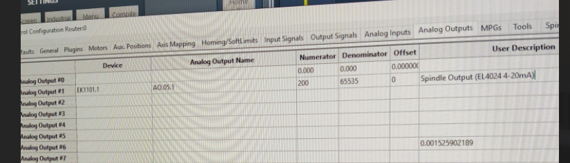
You can add the analog outputs to the dashboard by adding a Analog Function and then select the analog outputs you want to add.

Probing
RapidPath supports up to ten probe signals. The probe signals should be mapped to the corresponding I/O point in the control configuration. Any of the Beckhoff I/O points can be used as probe inputs. If a probe is wired into a servo drive directly, then it must be wired into latch inputs on all drives or must also be wired into a Beckhoff I/O.
It is not recommended to wire probe inputs to the latch signals on the servo drives.
The basic Probe signal corresponds to the gcode G31. All subsequent probe signals correspond to G31.#, where # is their probe index. For example, the Probe9 signal is gcode G31.9.
It is highly recommended to use a Beckhoff I/O for probe inputs and use the Motion Controller probe source for all motors.

Verifying Signal Mapping
All enabled signals can be seen on the main screen by going to the Service -> Machine I/O page. There will be a list of enabled input signals, a list of enabled output signals, and a list of I/O points. The input signals and output signals will be populated automatically from all enabled signals in the configuration window. They will be labeled by the user description field if it was filled out; otherwise, it will be the default signal name. Each signal will have a green LED next to it if the signal is currently on. Output signals can be turned on manually by double-clicking on them in the list.
It is recommended to verify input mappings by manually triggering inputs and verifying they are reflected on this page.
Use caution when manually activating output signals.
I/O points can be manually added to the I/O list.
- Right-click on the list and select Configure Widget.
- Select the device that owns the I/O point you would like to add.
- Select the I/O point from the list.
- Press Add to add it to the I/O list.
- Press Close to close the configuration window.
To remove an I/O point from the list:
- Right-click on the I/O point in the list to remove.
- Select Remove X, where X will be the name of the I/O point.

Using Signals In Gcode
The 64 general purpose output signals can be controlled from gcode using the mcodes M220 and M221. The gcode can wait on one of the 64 general purpose inputs to be a certain state with mcode M222. For more information, refer to the Mach4 Advanced M-Code Reference manual.
M220 S2 D2000 	(Turn on Output #2 and wait 2000ms)
M222 S1 T5		(Wait up to 5 seconds for Input #1 to turn on)
M221 S2	D1000	(Turn off Output #2 and wait 1000ms)
M222 S1 T10 I1	(Wait up to 10 seconds for Input #1 to turn off)
Spindle Configuration
Servo Spindle
The following instructions are for configuring a servo spindle as the main spindle on the machine. Some machines, such as centerless grinders, may be using a servo spindle as an auxiliary spindle or subspindle. See Auxiliary Spindles for more information.

Servo Spindle as Main Spindle

Yaskawa VFD Parameter Programming
Hitachi VFD Parameter Programming
Servo Spindle as Auxiliary Spindle
There are multiple types of auxiliary spindles available, depending on your machine type. The servo spindle must first be told it is an auxiliary spindle, and then it can be mapped to an available type. See Auxiliary Spindles below for further instructions.
Analog Spindle
RapidPath has support for one analog spindle, which must be the main spindle.
- Properly map the analog output in the control configuration. See Assigning I/O to Analog Signals for details.
- On the menu bar, click Configure -> Plugins -> RapidPath, then select the Parameters tab.
- Go to the Analog Spindle section.
- Set the Spindle Analog Output Signal to the analog signal that is mapped to the analog output.
- Select the appropriate Spindle Type for your analog output.
- Click Close.
- On the menu bar, click Configure -> Control, then select the Spindle tab.
- Set the Max Spindle Motor RPM parameter appropriately.

For +/- analog controlled spindles:
For 0-10V analog controlled spindles:
VFD
This section is for EtherCAT VFDs.
Current build of Mach needs in the rapid path plugin VFD Command Mode set to RPM, in machmotion plugin Output Command Type set to Percentage, and Control Source Command Type set to Percentage. Noticed on 7/24/23
The RapidPath motion controller integrates to Yaskawa EtherCAT VFDs V1000, A1000, GA500, and GA800. The RapidPath motion controller can also work in conjunction with modbus controlled VFDs.
Device Identification
Similar to servo drives and couplers, VFD objects will index up along the network. The first VFD on the network will be identified by its name followed by ".1". Subsequent VFD devices will increment up from there.

VFD as Main Spindle
VFD as Auxiliary Spindle
There are multiple types of auxiliary spindles available, depending on your machine type. The VFD must first be told it is an auxiliary spindle, and then it can be mapped to an available type. See Auxiliary Spindles below for further instructions.
Spindle Testing
The spindle can be tested as follows:
Check interferences and use low speeds when testing a spindle.
- Enable the machine by pressing Reset.
- Type an RPM into the spindle speed DRO on the main page.
- Press FWD or REV on the operator panel.
- The light on the button will blink until the spindle gets up to speed, then turn solid.
- Press STOP to turn the spindle off.
- When stopped, the spindle should be able to be turned by hand.

Troubleshooting
- Make sure there is a speed commanded.
- Make sure your spindle rate override is at 100%.
- Make sure the correct digital outputs are mapped to the Spindle Fwd and Spindle Rev signals.
- Make sure the correct digital inputs are mapped to the Spindle At Speed and Spindle At Zero signals.
- Make sure the relevant Control and Feedback parameters are set to Mach.
Auxiliary Spindles
Some machines have multiple spindle devices that need to be controlled independently, such as centerless grinders. Servo spindles and VFDs can be set up as auxiliary spindles. First set the spindle device as auxiliary, then see some of the options below.
Subspindle
Most often used on router-type machines, the subspindle acts as a traditional spindle with it's own commanded speed, separate from the main spindle. It is commandable from gcode and MDI with M103 S#### (Subspindle Forward), M104 S#### (Subspindle Reverse), and M105 (Subspindle Stop).
Only VFDs can be configured as subspindles.
If the subspindle runs backwards, swap the values of the Sub Spindle CCW Output and Sub Spindle CW Output parameters.

Centerless Grinder - Grind Wheel
The grind wheel on centerless machines can be controlled as a VFD or a servo spindle.

Centerless Grinder - Reg Wheel
The regulating wheel on centerless machines can be controlled as a VFD or a servo spindle.

Additional Configuration
There are many custom configurations available for all machine types. Some more common options are covered below.
Lube System
Full documentation for setting up a lube system is located here.
Dual Table Routers
Full documentation for setting up a dual table is located here.
Global Monitoring System
The Global Monitoring System allows the user to set up monitors on the machine. A monitor watches a set of conditions and when all conditions are true, will take a predefined action. Full documentation is located here.
Screen Customizations
On most controls, there are three dashboards on the screen that are configurable for user needs. The far-right panel on the screen, the five buttons underneath the position DROs, and the Service -> Dashboard page. To configure these areas, right-click on them and select Configure Dashboard. For more information, see Dashboards. For more advanced screen customizations, call MachMotion.
Operator Panel Function Buttons
The 2000 Series operator panels and the wireless pendants have up to eight configurable function buttons available. These buttons can be assigned to predefined options. Not all options will exist on all systems. If you have a functionality need that does not exist on the machine, call MachMotion.
Diagnostics
Overview
RapidPath diagnostics gives the operator a variety of information about the network and individual devices. It also has some necessary functionality in it that is not accessible elsewhere in the control.
Accessing RapidPath diagnostics:

Network I/O
The first page in diagnostics shows all I/O points on the network, split by device and approximate layout. This is updated live with the actual I/O states. Double-clicking on an output will change the state of the I/O.
Manually activating I/O can have unexpected results on the machine and control.
Motors
All motors on the network are listed here. For each motor, there is the following information:
- Assigned Axis
- EtherCAT Commanded Position
- Core Commanded Position
- Actual Position
- Position Error
- Current Motor RPM
- Current Motor Torque Percentage
All positions are listed in encoder counts.
Network Diagnostics
The network diagnostics page has data about network health and operability. It also maintains logging for RapidPath messages. The verbosity of RapidPath logging can be managed here, with the logging level slider.
Inputs/Outputs
The Inputs/Outputs page shows all network I/O and all virtual I/O maintained by the RapidPath plugin. It is updated live with the actual I/O states. Double-clicking on a line will toggle the state of the I/O.
Manually activating I/O can have unexpected results on the machine and control.
Registers
The Registers page shows all registers owned by RapidPath, organized by device, along with their current values. It is updated live with actual register values. Double-clicking on a line will open a window for editing it.
Manually changing registers can have unexpected results on the machine and control.
Services
The current state of the lower level EtherCAT network services are shown on this page. Manually restarting the network can be done on this page.
Manually managing the EtherCAT services can have unexpected results on the machine and control.
Device Functions
Some devices have specific functionality that must be accessible to the operator during machine set up outside of configuration. Those devices will be listed on this page. Selecting a device will show the options available.
RapidPath
Syncing Slaved Motors
When first slaving motors, their encoder positions must be aligned to prevent runaway motion when enabling. This page has a button for each axis to sync it's motors. If an axis has no slaved motors, the button will not be enabled.
Troubleshooting
Motion Graph
Run a "setup" script first. It should be located in MACH_DIR\tools\DataVisualization\install_python_prerequisites.cmd
Under Service - Maintenance, select View CMDs List.

Then search for capture. Select RapidPath Toggle Capture Motion Data. Then select Run Command to start recording positions. Press Run Command again when you want to finish recording positions.

Wait after the 2nd time you press the Run Command and it will pop up with a graph viewer.

To see a graph, select the file to run and then one of the option buttons on the right.
To re-open a previous graph, run the Data Visualizer.

Motion Scope
There is a tool built into the RSI RapidSetup software called MotionScope which provides both a visual graph of motion, and an exported fixed column width file. On a MachMotion control computer, these are the basic steps to run MotionScope and capture data that can be reviewed by MachMotion.
There should be a desktop shortcut to the MachMotion Programs, and RapidSetup is in that folder.

You need to run the RapidSetup program, then open the MotionScope program from within RapidSetup.

Once MotionScope is running, you should close RapidSetup as you no longer need it running.
You will need to select the data that you want to see when the machine is in motion. A good starting set is the commanded motion, the actual motion, and the difference between them – the position error. Depending on the circumstances, acceleration and velocity may also be helpful. Note that position error will always increase as the velocity increases. Once the velocity has reached the desired value, the position error should also stay at the same value.

You select the data by clicking the Traces button and selecting parameters, then adding them to the trace list. When you have selected the parameters, close the traces window and click the Arm button. That will prepare the software for capturing data from the machine.
This is a “Full Out” view of motion with all of the above parameters being graphed.

The yellow vertical rectangle has a lot of data, but is difficult to sort out at this zoom level. If you click the “Step In” button several times, it will show the data clearly.

At this level you can see the problems, and can then export the data to a text file, or capture screen shots of the problem.

To save to a file, select the Pane menu, then Export. Save the data to a text file. This data is the full set of data points used to create this graph.
To convert counts to units, use this formula:
Counts from the Graph / Steps Per Unit = Units
Rapidpath Will Not Initial
Delete all entries of RMPECAT in the Machine.ini. The main nodes and each of the details in the sub sections.
NOTE: You will lose all your node specific settings like IO mapping.

For example, delete the following section.
[RMPECAT_1.5_Beckhoff_-_DO8_00000002_07d83052_0]
AnlgIODatumCount=0
AssignedProfile=Jet
DEVConfigFileBase=DeviceInfo.INI
DeviceName=EK1100.1
DisconnectedMotor=0
DisplayName=EK1100.1/DO.05
DisplayNameOverridden=0
EtherCAT_NodeID=RMPECAT_1.5_Beckhoff_-_DO8_00000002_07d83052_0
EtherCAT_NodeNumber=7
GenericSoftInputCount=0
IOConfigFileBase=Beckhoff_-_DO8_00000002_07d83052.INI
IODatumCount=0
IsDeviceControlled=1
MachInstance=0
MotorClass=1
NodeName=Beckhoff - DO8
ProductCode=131608658
Revision=0
SerialNumber=0
StationAlias=0
VendorID=2
You should not be able to find RMPECAT in the Machine.ini at all if done correctly.
Warranty Information
MachMotion warranty policy is subject to change. Updated information is available at our website:
https://machmotion.com/warranty
The MachMotion Team
http://www.machmotion.com
14518 County Road 7240, Newburg, MO 65550
(573) 368-7399 • Fax (573) 341-2672